AE/LZB 119 1902 R1A
30
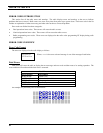
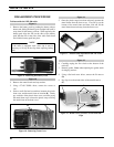
Figure 17
14. Pry up on the hook to release from the latch and push
down on the switches to remove the assembly from the
housing.
Figure 17 - Removing Switch Assembly
(Pry up on the latch)
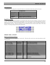
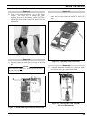
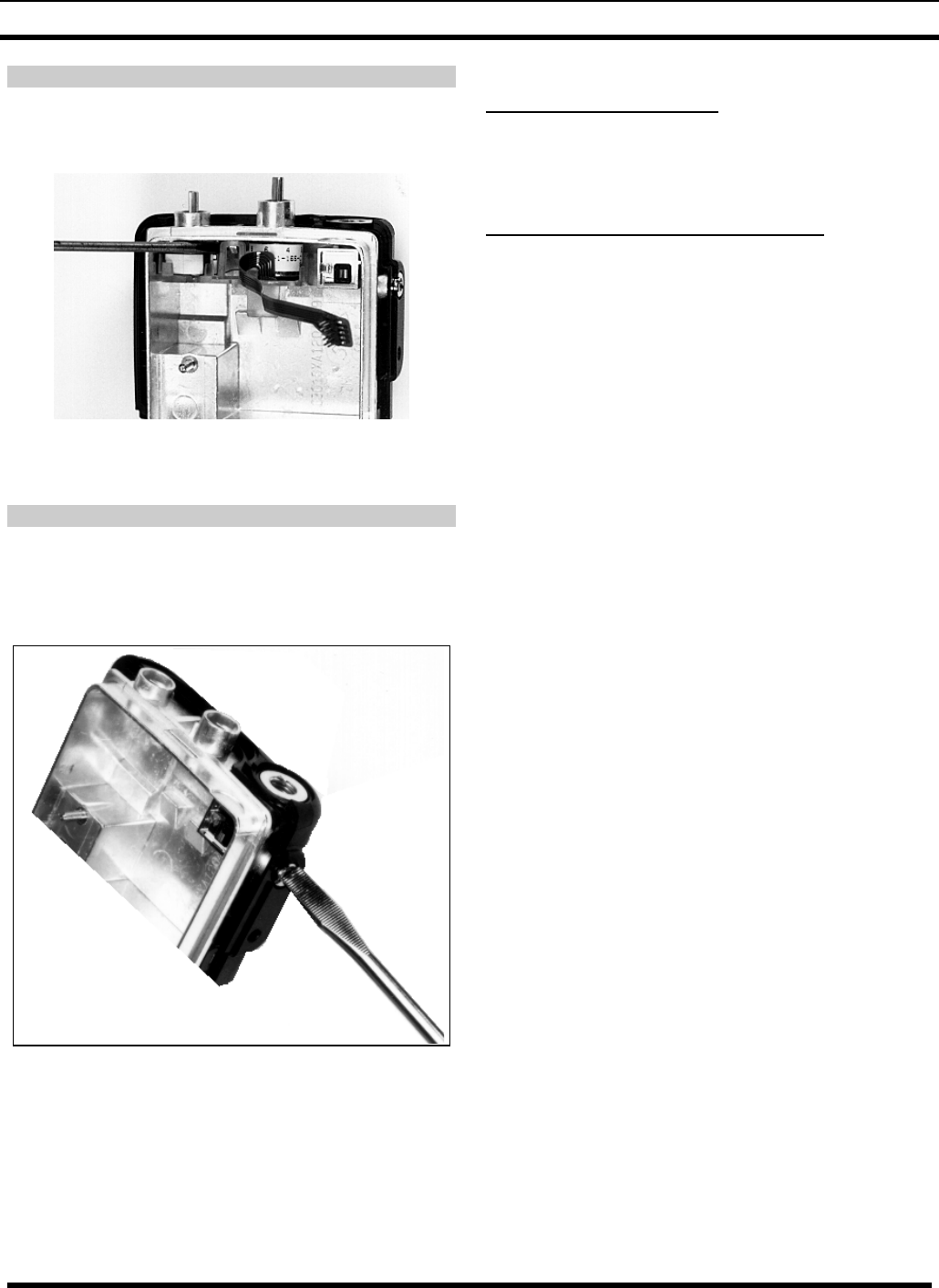
Figure 18
15. To remove the Antenna Switch Assembly the switch
assembly must be removed first.
16. Unscrew the RF nut. Remove the switch being careful
not to lose the washer.
Figure 18 - Removing the Antenna Switch
PA Module Replacement
Remove the PA Module by unsoldering the five (5) leads
attached to the Main Board (see the Outline Diagram).
Solder new module in same location.
Filters Z400 And Z401 Replacement
Filter Z400 has four (4) leads that go all the way through the
board and are soldered on the reverse side of the board.
Unsolder the four leads to remove Z400.
Filter Z401 also has four leads. But Z401 is surface
mounted on the same side of the board. Unsolder the leads
to remove Z401.
REASSEMBLY
Reassemble the radio by reversing the instructions
(steps 1-16) provided in the Dissassembly Section.


