


AE/LZB 119 1902 R1A
17
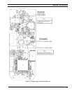
Tx Switch (V192)
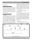
The Tx Switch consists of transistor V192. Transistor
V192 is normally off (receive). When the Delayed Push-To-
Talk (DPTT) line goes high (transmitter keyed), transistor
V192 conducts and the base of B+ Switch PNP transistor
V191 goes low.
B+ Switch (V191)
B+ Switch transistor V191 supplies 7.0 volts to the
directional coupler in the antenna circuit. When the base of
this PNP transistor goes low, 7.0 volts is on the collector
and can be metered at test point TP191. This voltage goes
to directional coupler W100, Pin 1 (PORT 1). The B+
Switch circuit and the TX Switch circuit are tagged
BUFFER
on the Block Diagram (Sheet 1 of the Schematic
Diagram).
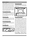
Analog Regulator (N900)
Battery voltage connects directly to analog regulator
N900, Pin 8 (
Input
). Capacitor C900 provides filtering at
this point. To enable N900, Pin 3 (EN) must be grounded.
This is accomplished by grounding one end of resistor R912
when the power switch is turned on. The voltage divider
relationship between pull-up resistor R909 and resistor R910
is enough to produce a ground which will enable N900.
This signal is typically < 0.6 Volts when the radio is on and
> 2.0 volts when the radio is off and can be metered at test
point TP904. The ground at R912 can be metered at test
point TP907 and is 0 Vdc when the power switch is on and
7.5 Vdc when the power switch is off. When enabled, the
output on N900, Pin 1 is a regulated +5 Volts. This voltage
can be metered at test point TP901. Filtering is provided by
capacitor C901. The output of N900 becomes the
+5V_A
line. The +5V_A connects to the base of transistor V905,
causing V905 to conduct. Transistor V905 conducting
causes the collector (
PWR_ENABLE_B
) to go low and
enable the RF regulators. The +5V_A also goes to the
emitter of PNP transistor V906. This caused V906 to
conduct placing an active high on the Shut Down (
SHDN
)
input of +5V_D switching regulator N902. The +5V_A also
goes to the TX/RX audio circuits in DEBBIE (D601).
+5V-D Switching Regulator (N902)
B+ is connected to N902, Pins 1, 15 and 16 (
U+
).
When an active high is on N902, Pin 2 (
SHDN
), N902 turns
on and produces
+5V_D
on the output to power all digital
circuits.
Processor Reset
+5V_D is connected through resistor R901 to open
collector output N900, Pin 5 (
ERROR
). Timing is provided
by pull-up resistor R901 and capacitor C905. The ERROR
voltage can be metered at test point TP903. This voltage is
normally + 5 Volts or 0 Vdc on reset. This voltage also
connects back to N902, Pin 7 (SS) Soft-Start. When
capacitor C905 charges up, the output of buffer gate D900
goes high. This high on D701, Pin 1 (
RESPOW_B
) starts
the processor.
Power Switch Turned Off
Due to software programming, when the power switch
is switched off, the power to all circuits may not be
immediately turned off. For example, the processor may
need to transmit log off messages before that happens.
When the radio is turned on and the processor is started, a
PWR_LATCH
signal (2.6 Volts) is applied to the base of
transistor V903 turning it on. The collector of V903 goes
low and the enable line to N900 is latched in a low state,
holding N900 on. N900 can be held on indefinitely if
programmed to do so. A
PWR_SW_SENSE
line monitors
the condition of the power switch so the processor knows
when to start the power down program. When the power
switch is on, diode V904, Pin 3 is low. The +5V_A through
resistor R911 forward biases V904 and holds the
PWR_SW_SENSE
line low. When the power switch is
turned off, the diode is no longer forward biased. Pull-up
resistor R911 now pulls the
PWR _SW_SENSE
line high to
indicate to the processor that the power switch has been
turned off.
Low Battery Power Down
The battery voltage is monitored with A/D input to
ATTIE. To protect the battery against deep discharge
conditions a
LOW_BATT_PWR_OFF
line is provided to
shut the radio down until a fresh battery is attached. When
the battery voltage falls below 5.6 Volts, diode V900 is
forward biased conducting through V902. When the
LOW_BATT_PWR_OFF
line is switched high, V901 and
V902 latch on forcing enable pin N900-3 high, which results
in shutting the radio off.