


AE/LZB 119 1902 R1A
13
TRANSMITTER
Transmit Frequency Generation
The main VCO, in the synthesizer circuit, is
programmed to generate the 1st
LO
receive injection
frequency (1011.2 to 1016.2 MHz). This carrier frequency
is mixed with a transmit offset frequency of 115.2 MHz to
generate the carrier and two side band frequencies. The
carrier and upper side band are suppressed and only the
lower side band is transmitted. For example: the carrier
frequency of 1015.2 MHz minus the offset frequency of
115.2 MHz is equal to the transmitted lower side band
frequency of 900 MHz.
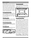
TX/Converter/Modulator (N150)
Transmit Offset
The
LPE-200
transmit offset frequency is 115.2 Mhz.
This frequency is generated by a seven-times-multiplier
circuit off the reference oscillator. The output of this VCO
is applied to a
P
hase-
L
ock-
L
oop (
PLL
) where it is divided
by 7 (115.2 ÷ 6 = 19.2 MHz) and compared to a reference
frequency of 19.2 MHz. The 19.2 MHz reference frequency
is generated by oscillator module U201 in the synthesizer
circuit. A DC phase lock voltage, which is the difference of
the two input frequencies, on N150, Pin 9 (
PHSOUT
) is
applied to a loop filter. This loop filter consists of
capacitors C151, C152 and C155 and resistors R153 and
R154. The DC voltage can be metered at test point TP150
and should be 1-4 volts while transmitting and 0 volts while
receiving. The output of the filter connects to the tank
circuit through resistors R155 and R160. The tank circuit
for the VCO and consists of capacitors, C160, C161, and
two variable capacitors in V180 and inductor L154. The
loop filter and the tank circuit are tuned to 6x19.2 MHz or
115.2 MHz. The tank circuit connects across N150, Pins 6
(
TANK_1
) and 7 (
TANK_2
). The DC voltage applied to
the loop filter changes the capacitance of the variable
capacitors within V180 of the tank circuit to maintain the
VCO output of 115.2 MHz.
When the transmitter is keyed, transistor V152 conducts
to increase the bandwidth for PLL acquisition.
Single Side Band Mixer
The main VCO frequency is amplified then passed
through a 90-degrees phase shifting network to the SSB
mixer. The 115.2 MHz offset frequency is also amplified
and passed through a 90-degree phasing network to the SSB
mixer. These two signals are summed together to produce
the carrier frequency, an upper side band and a lower side
band. The carrier and upper side band are suppressed by 40
dB. The lower side band passes at full amplitude. There are
two outputs of the lower side band from the SSB, each 90-
degrees out of phase. Each signal is connected to another
mixer circuit where it is summed with the transmit
modulation from HILLARY. Resistor R159 sets the gain
for phase detection.
Low Pass Filters
There are two modulating inputs from HILLARY, one
is the
I
input (
MODI
and
MODI_B
) and one is the
Q
input
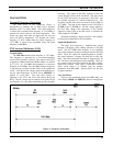
Figure 4 - Frequency Generation