


AE/LZB 119 1902 R1A
10
CIRCUIT ANALYSIS
The portable radio is unique in the generation of the
transmit carrier. The transmit section has an offset
frequency loop operating at 115.2 MHz. This means the
synthesizer is operating at a frequency that is not
harmonically related to the output frequency.
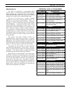
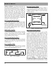
The radio contains five custom integrated circuits as
follows:
•
DEBBIE
(D601) - Has three major functions:
digitizing, voice CODEC and digital to analog
conversions.
•
HILLARY
(D701) - Contains the microprocessor,
phase digitizer, frequency discriminator and sigma/delta
modulator to provide digital modulation.
•
JACQUI
(N150) - Generates the transmit carrier
frequency from the main VCO frequency. Generates
the transmit offset oscillator frequency and provides
modulation through the I/Q inputs.
•
CHERYL
( N203) - The main and auxiliary frequency
synthesizers for the main VCO and the 2nd Local
Oscillator (LO).
•
DIANE
(N551) - Contains the 2nd mixer and the LO
for the 2nd mixer. Contains a limiter circuit which
provides a balanced output to HILLARY. Provides the
receiver 2nd IF and the
R
eceiver
S
ignal
S
trength
I
ndicator (
RSSI
) signal.
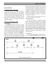
The Schematic Diagram for this unit consist of 16
sheets. Component coordinates are provided so the
technician can locate different points with ease. For
example: A point may be labeled
7-B16
. This means that
this point connects to a point shown on sheet 7 with
coordinates
B
(read up) and
16
(read right). Borders with
vertical and horizontal coordinates are provided to facilitate
this capability.
SOFTWARE
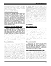
Software in the microprocessor handles basic radio
controls, interfaces and system protocols. The HILLARY
chip and DSP handles all modulation, demodulation and
speech processing functions.
Microprocessor software consists of:
•
RAM Bootloader Software
- downloaded by the PC
programmer into the radio and executed. This software
communicates with the PC using a full network protocol
(x3.28). Serial data is transferred through the radio
UART for FLASH application loading, DSP code
storage and personality storage. This software supports
read/write of EEPROM data such as Tracking Data and
Feature Encryption. Data compression is used to
reduce FLASH application loading time.
• FLASH Application Software - the main radio
controller software. It is divided into the platform and
application modules. The platform software provides
the hardware level interface, operating system, run-time
libraries and software standby (sleep) operation. The
application software provides all of the user interface
trunked signaling, conventional signaling, diagnostics,
debugging capability, UDC device support and
personality interface.
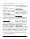
DSP software includes:
• FM Audio Processing - Transmit
• FM Audio Processing - Receive
• Transmit Waveform Generation
• Transmit Waveform Combinations
• Demodulation/Decoding
• Demodulation/Decoding Combinations
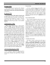
RECEIVER
RX Front End
The 935-940 MHz RF receive frequency is passed from
the antenna through a low pass filter/antenna switch to the
input of fixed ceramic band pass filter Z400 (Pin 1). The
band pass center frequency is 938 MHz and the gain through
the filter is typically -1.5 dB. The output of Z400 (Pin 2) is
coupled through capacitor C400 and impedance matching
inductor L400 to the base of RF amplifier transistor V400.
RF Amplifier (V400)
RF amplifier transistor V400 provides typically +16 dB
of gain to the RF signal. The gain of this stage is controlled
by feedback voltage from
IF AMP 1
transistor V500 which
sets the bias of V400. The emitter voltage of V500 is
connected to the collector of V400 through resistors R504
and R401, and filter capacitors C506 and C507. This
voltage can be metered at TP400. The bias to the base of
V400 is set by resistor R400. RF coil L401 tunes the
amplifier load. The output of V400 is coupled through fixed
ceramic band pass filter Z401 (Pin 1). The band pass center
frequency is 938 MHz and the gain through the filter is
typically -1.5 dB. The output of Z401 (Pin 2) is connected
to the input of mixer circuit Z402 (Pin 5).