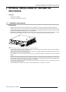
3. Physical installation of the DMP-100 processor
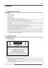
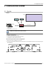
3.2 Connections of the DMP-100 processor
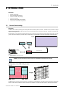
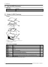
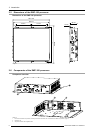
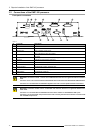
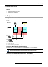
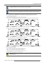
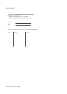
Front panel connections
1 2 3 4 5 6
7 8 9 10 11
Image 3-2
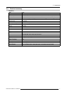
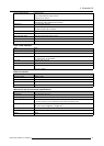
Nr.
Connector
Description
1
USB interface Common USB interface for the embed ded PC.
2
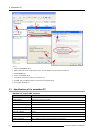
USB — UART interface USB interface for external control PC w hich can be used to update software or firmw a re .
3 Indicator light PWR: indicates power sup ply.
MCU: indicates the MCU work status.
4
RS-232 Used by RMS software on an external control PC to communicate with the D MP -100
processor.
5
LED interface DVI Output t o LED wall (Barco proprietary protocol).
6 DVI input External DV I source signal input port.
7
COM 1 Embedded PC COM 1 port .
8 Ethernet interface Embedded PC E thernet interface for remote control.
9 Mouse interface Embedded PC mouse / Keyb oard port.
10 VG A interface Embedded PC VGA display port.
11 USB interface Embedded PC USB port.
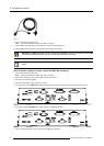
WARNING: Con nectors number 1, 2 and 11 are a ll USB interfaces but there is a significant difference b etween
them .
Connector 1 and 11 are connected with the em bedded P C b oard and are therefor embedded PC US B in terfaces.
Connector 2 is connected with the embedded d igitizer board and is used to update software a nd firmware.
WARNING: Connectors n um ber 4 and 7 are b oth RS—232 interfaces b ut there is a significant difference be-
tween them.
Connector 7 is connected with the embedded PC bo ard an d is therefor an embedded PC COM 1 port.
Connector 4 is connected with the processor b o ard and is used by the external control PC to communicate
with the DMP-100 processor.
12 R59770263 DMP-100 15/09/2011