


9SilverBoom 300
www.silverstarlifts.com
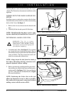
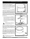
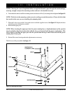
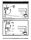
Figure 4. L-Base (Trunk Installation)
WHEEL WELL
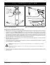
TRUNK INSTALLATION (SILVERBOOM
300 MANUAL ROTATION ONLY)
Position the L-base as shown in figure 3. You may need
to situate the L-base so the wheel well does not interfere
with the L-base extensions. Ensure there is adequate room
for a mobility product to comfortably fit into the trunk.
III. INSTALLATION
ASSEMBLING THE LIFT
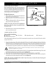
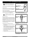
1. Insert the upper post into the L-base. See figure 5.
NOTE: When inserting the upper post into a power
rotating base, a slight adjustment of the sprocket
may be needed to align the insertion hole of the
sprocket with the lower post located inside the power
rotating base. This can be done by inserting the
upper post into the sprocket hole and moving it until
the upper post descends into the power rotating
base’s lower post.
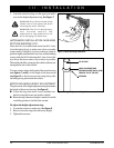
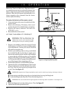
2. Slide the height adjustment ring (see figure 6) over
the upper post and tighten the setscrew (a good start-
ing point is approximately 12 in. (30.5 cm) down
from the top of the upper post). See figure 4. To
ensure safe operation, the height adjustment ring must
be secured no closer than 6 in. (15 cm) from the top
of the upper post.
WARNING! Failing to tighten the
height adjustment ring setscrew
could cause damage to your lift,
mobility product, and vehicle.
NOTE: The height adjustment ring may need to be
adjusted down so the boom-arm has sufficient head
room to swing into a vehicle, or adjusted up so the
mobility product being lifted has ample room to
clear obstructions.
NOTE: If the length of the upper post for the
power rotating base needs to be made shorter dur-
ing installation to ensure a proper fit into the ve-
hicle, a qualified technician should remove the up-
per post cap, cut the necessary length from the
top of the post, then reinstall the upper post cap
See figure 13A.
PROHIBITED! Do not cut any length
from the bottom of the upper post of
the power rotating base.
L-BASE
UPPER POST
HEIGHT ADJUSTMENT RING
Figure 5. Upper Post Installation
!
!
MINIMUM OF 6” (15 CM)
Figure 6. Height Adjustment Ring Assembly
SETSCREW