


13SilverBoom 300
www.silverstarlifts.com
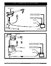
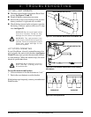
ELECTRICAL WIRING INSTALLATION
1. Route the lift’s long power wire (starting at the lift) through the interior of the vehicle until you reach the
automobile battery. See figure 13 and 13A. Conceal the wire behind or under the interior panels (there
should be existing holes). Be certain that the wire is protected with a rubber grommet when passing it through
the metal panels and into the engine compartment. Inside the engine compartment, secure the wire to the
firewall and the inner fender with the supplied plastic wire ties. Use care not to cause abrasions to the power
wire. It is important to secure the power wire at various points along its run.
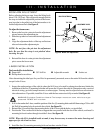
2. Insert the red positive (+) lead on the power wire into the spliced end of the red positive (+) battery lead, then
crimp the splice to secure the wire.
3. Connect the red positive (+) battery lead to the positive (+) battery terminal and the black negative (-) ground
wire to the negative (-) battery terminal.
WARNING! The red positive (+) wire must be connected directly to the positive (+) battery
terminal.
WARNING! The black negative (-) wire must be connected directly to the negative (-)
battery terminal.
4. Connect the harness extending from the motor housing to the harness coming from the battery (black to black
and red to red).
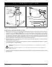
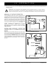
III. INSTALLATION
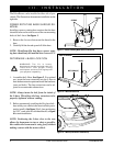
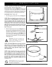
Figure 11. L-Base Cap Installation
L-BASE CAP
PHILLIPS HEAD SCREW 10 MM
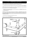
Figure 12. Fully Assembled Lift (SilverBoom 300 Shown)
L-BASE
UPPER POST
L-BASE CAP
MOTOR HOUSING
T-BAR