


20
CHAPTER 4
21
CHAPTER 4
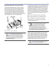
Using the LD-3
In addition to the 160 Hz high-pass lter on the LD-3, the
LD-3 compensating line driver provides additional ltering
capabilities to help you further ne-tune an M2D/M2D-Sub
system.
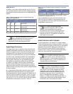
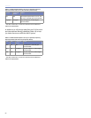
Table 4.2: M2D and M2D-Sub frequency response results with
different lter congurations
HPF LPF ø Reverse
Switch
Result
Off Off Off Flat response (small rise on 70 Hz
-160 Hz area)
80 Off Off Very at response, +3 dB sub gain
recommended
80 80 Engaged Very at response, +3 dB sub gain
recommended
160 OFF Engaged Very at response
NOTE: For more information on the LD-3 line
driver’s atmospheric and array correction
features, please refer to the LD-3 Operating
Instructions or visit www.meyersound.com.
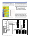
Digital Signal Processors
Full-range signals may be applied to Meyer Sound’s self-
powered loudspeakers because they have built-in active
crossover circuits; external crossovers and digital signal
processors (DSP) are optional and should be used very
carefully due to phase shifts that can cause cancellations.
If a DSP is used, both M2D and M2D-Sub loudspeakers
should be fed from the DSP in order to keep their delay
time the same. Otherwise you may experience phase
shift differences between the M2Ds and the M2D-Subs.
In addition, you should verify the delay time between
channels: Some DSPs may develop channel-to-channel
delay errors when the DSP is near maximum throughput,
which becomes more likely as the number of lters the DSP
is using increases.
In no case should a lter higher than 2nd-order be used.
The additional phase shift introduced by steep sloped
lters deteriorates the impulse response and higher roll-off
does not improve crossover interaction. In fact, it is highly
recommended that the crossover/lter are set to emulate
the low-cut LD-1A, LD-2 and LD-3 (at the 160 Hz position)
characteristics themselves, as shown in Table 4.3.
Table 4.3: LD-1A, LD-2 and LD-3 (LD-3 at 160 Hz) “Lo-Cut Filter”
Parameters
Type Order Pole
Frequency
Q
High Pass 2
nd
(-12 dB/oct) 162 Hz 0.82*
* If the DSP does not have variable Q for high-pass lters, the lter
should be set to “Butterworth” (Q ≈ .7).
If the loudspeakers are going to be driven directly from
DSP, verify that the outputs of the processor have the
driving capabilities to drive the total load presented by the
loudspeakers connected to it.
NOTE: When precise array design,
subwoofer integration, DSP and delay
systems, and compensation for acoustical
conditions all come into play, measurement and
correction tools are a must. Meyer’s SIM audio
analyzer and the CP-10 parametric equalizer are
both highly recommended.
USING THE 650-P WITH THE M2D
In some applications – for instance, in a system design
where the subwoofers do not need to be own in the array –
it may be desirable to deploy an M2D array in combination
with Meyer Sound’s 650-P high-power subwoofer. The
650-P subwoofer extends the M2D system frequency
response down to 28 Hz, and can accommodate daisy-
chain, line driver, and DSP connection options.
NOTE: The 650-P subwoofer does have a
polarity switch, and you will need to ensure
that it is set to pin 2 + (same polarity respect to the
M2D loudspeaker’s pin 2 +) when co-planar and in
close-proximity to and M2D array.
NOTE: When driving M2Ds from the Mid-
Hi output of the LD-1A, LD-2 or LD-3 line
driver with the Lo-Cut lter engaged and 650-P
subwoofer in their full-range conguration, their
polarities should be kept the opposite if they are
co-planar or near each other. If your M2D and
650-P loudspeakers are separated by a greater
distance – or delay must be used between them – a
measurement system such as SIM should be used
to determine the correct delay and polarity.