


20
CHAPTER 4
21
CHAPTER 4
In addition, the use of high-pass lters to drive an M2D
system with the M2D-Sub attens overall frequency
response and slightly increases M2D headroom in the
lowest end of its usable spectrum.
The ideal ratio of M2D to M2D-Sub loudspeakers depends
on the conguration of the system, the application, and the
frequency content of the signal being reproduced. For most
applications, two M2Ds for each M2D-Sub yields good
results in frequency response and headroom.
NOTE: The M2D-Sub limit LEDs indicate
when its safe power level is exceeded. If
the M2D-Sub loudspeakers used in a system begin
to limit before reaching the required SPL at low
frequencies, you may need to add more M2D-Subs
to satisfy the SPL requirements without exposing
the drivers to excessive heat and/or excursion.
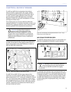
The M2D and M2D-Sub loudspeakers can accommodate
three basic connection options.
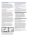
Daisy-Chained
When M2Ds and M2D-Subs are daisy-chained using the
loop feature on the user panel, the result will have a fairly
at frequency response. However, at a ratio of two M2D to
each M2D-Sub loudspeaker, the response will have a rise in
the 70 to 160 Hz range where the frequency of the M2D and
M2D-Sub overlap.
CAUTION: Always ensure that the source
equipment can drive the total load of the
paralleled system.
NOTE: When both and M2D and M2D-Sub
loudspeakers are used in their full-range
conguration (e.g., looped audio or the same audio
feed), their polarities should be kept the same if
they are co-planar or near each other. If they are
separated by a greater distance – or delay must
be used between them – a measurement system
such as the SIM audio analyzer should be used to
determine the correct delay and polarity.
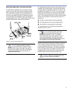
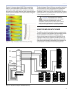
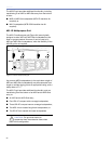
Adding a Line Driver
Driving an M2D/M2D-Sub system with the same signal from
different outputs using a line driver allows adjustments to
the gain and polarity of each sub-system, and could be used
effectively to compensate for the ratio of loudspeakers or
acoustical conditions. If the gains are adjusted to the same
level, the combined response is identical to a daisy-chain
conguration with a rise in level on the overlapping range.
Meyer Sound makes available three different line drivers.
Engaging the Lo-Cut Filter
Using the LD-1A, LD-2 or LD-3 Lo-Cut lter (the 160 Hz
HPF position on the LD-3) can produce an M2D/M2D-
Sub system (in close proximity and co-planar) with very
at frequency response and a minimal area of overlap.
The M2D loudspeakers in the system receive their signal
following a high-pass lter, while the M2D-Subs apply their
normal internal crossover frequencies to a full range signal.
NOTE: When driving M2Ds from the Mid-
Hi output of the LD-1A, LD-2 or LD-3 line
driver with the Lo-Cut lter engaged and M2D-Sub
loudspeakers in their full-range conguration, their
polarities should be kept the opposite if they are
co-planar or near each other. This can be achieved
by engaging the polarity reverse switch on the
subwoofer output of the line driver. If your M2D and
M2D-Sub loudspeakers are separated by a greater
distance – or delay must be used between them
– a measurement system such as the SIM audio
analyzer should be used to determine the correct
delay and polarity.
TIP: How at the response will be is, in any
case, dependent on proximity to boundary
surfaces.
While the change of polarity with respect to a daisy-chained
conguration is needed due to the phase shift caused by
the high-pass lter at overlapping frequencies, placing
M2D-Sub loudspeakers more than 4 feet apart from M2D
loudspeakers may require reversing the polarities once
again to compensate for the delay propagation.
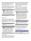
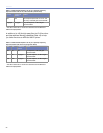
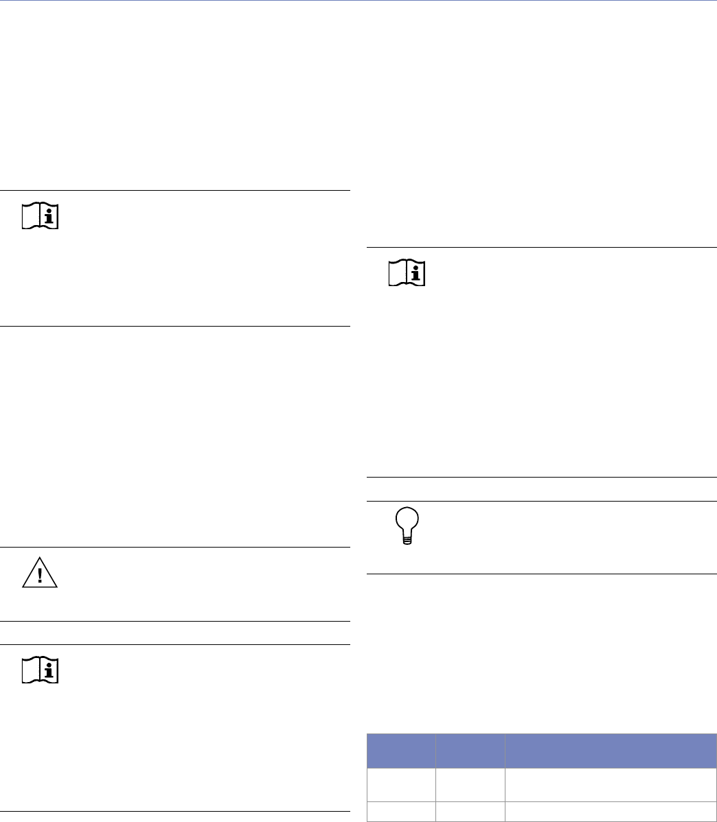
Table 4.1: M2D and M2D-Sub frequency response results with LD-
1A, LD-2 and LD-3 (160 Hz lter)
Lo-Cut ø Reverse
Switch
Result
Off Off Flat response (small rise on 70 Hz -160
Hz area)
Engaged Engaged Very at response