


15
CHAPTER 3
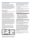
The M2D and M2D-Sub loudspeakers are tted standard
with an RMS communication module installed in the rear of
the loudspeaker. The RMS real-time networked monitoring
system connects Meyer Sound self-powered loudspeakers
with a Windows-based PC at the sound mix position or
other remote location. Optional RMS software delivers
extensive status and system performance data directly to
you from every installed loudspeaker.
RMS allows you to monitor amplier voltages, limiting
activity, power output, temperature, fan and driver status,
warning alerts, and other key data; data is updated two to
ve times per second.
NOTE: Optional Speaker Mute and Solo
functions, helpful for acoustic setup or
troubleshooting, are also available. An internal
jumper must be installed in the RMS communication
module in order to enable Mute and/or Solo
functionality; the software also needs to be enabled
for these functions.
The M2D and M2D-Sub loudspeakers are shipped
with these functions disabled. Once enabled,
the jumper(s) can still be removed to eliminate
any chance of an operator error (a muting error,
for example) during a performance, and both
functions can be controlled by software commands
in any case. Also note that RMS does not control
loudspeaker volume or AC power.
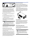
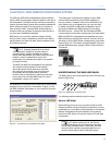
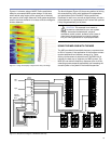
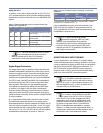
Loudspeakers are identied on the network by Node Names
assigned during a one-time “commission” (Figure 3.1) into
the RMS database that resides on your computer (as a part
of the software).
Figure 3.1. Commissioning a loudspeaker using RMS
This information is permanently retained on each RMS
communication module and in the RMS database un-
less you modify it. Speaker Titles can be modied at any
time, allowing you to customize how you view the data.
In addition, any M2D or M2D-Sub loudspeaker can be
physically identied from RMS software by activating
the Wink function – a Wink LED will illuminate the RMS
communication module that corresponds to its Node Name.
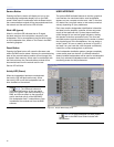
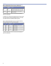
M2D and M2D-Sub loudspeakers are identied using the
RMS software by activating the “service” function; an icon
will show up on the RMS screen corresponding to its Node
Name (Figure 3.2). This makes verifying Speaker Titles and
speaker eld labels easy, using the Wink or Service Button
commands.
Figure 3.2. RMS loudspeaker icons
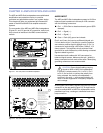
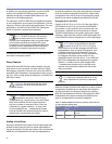
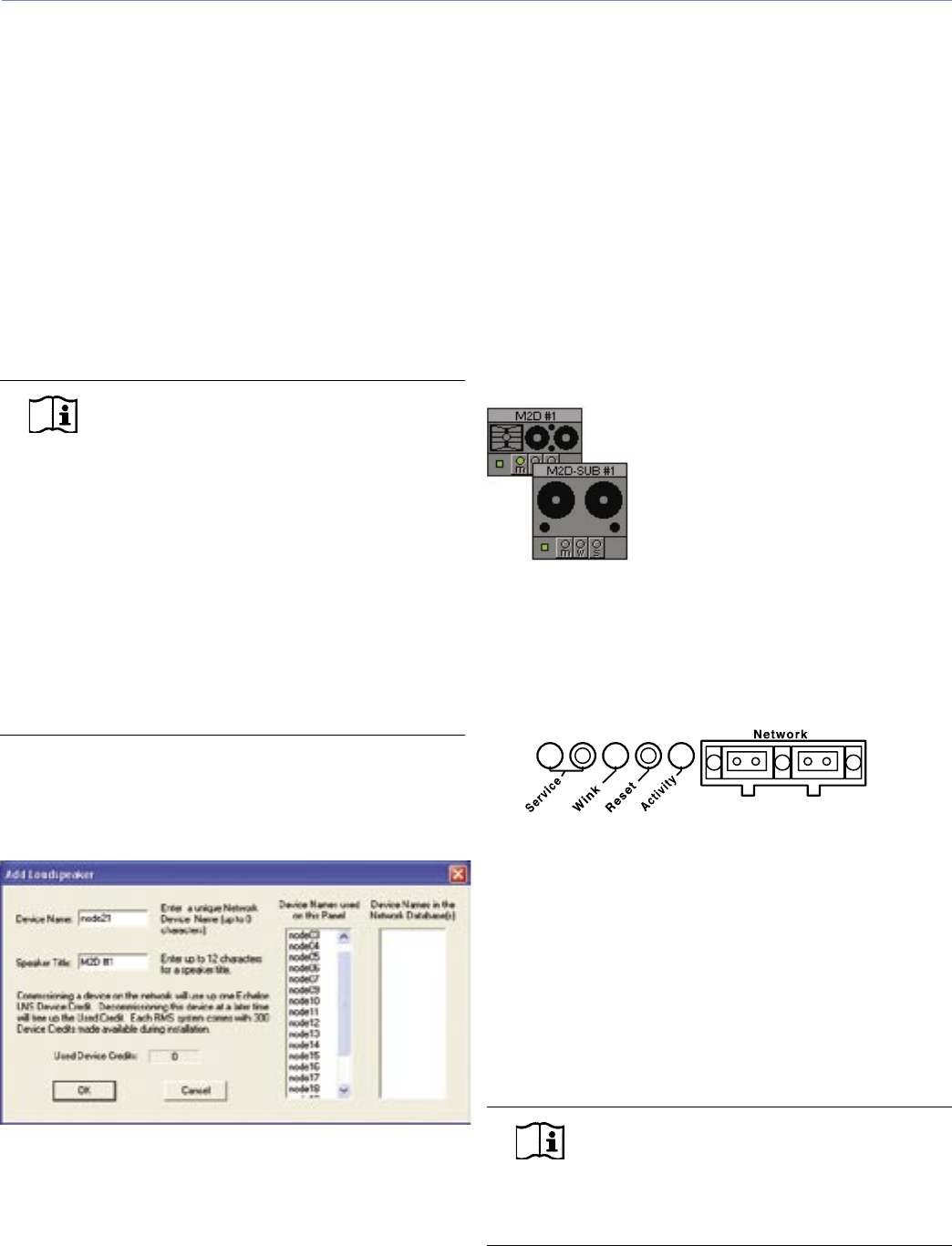
UNDERSTANDING THE RMS USER PANEL
The RMS section of the user panel has three LEDs and two
buttons (Figure 3.3).
Figure 3.3. RMS section of the user panel
The following sections describe their functions.
Service LED (Red)
When blinking once every two seconds, the Service LED
indicates that the network hardware is operational, but the
loudspeaker is not installed (commissioned) on the network.
When a loudspeaker has been installed on the network
the Service LED will be unlit and the Activity LED will ash
continuously.
NOTE: When continuously lit, the Service
LED indicates that the loudspeaker has had
a local RMS hardware failure. In this case, the RMS
communication module may be damaged and you
should contact Meyer Sound Technical support.
CHAPTER 3: RMS REMOTE MONITORING SYSTEM