


17
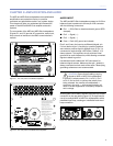
CHAPTER 4
A line array, in the most basic sense, is a group of closely
spaced loudspeakers arrayed in a straight line, operating
with equal amplitude and in phase. Although line arrays
have been used since the 1950s, line array systems that
provide full bandwidth directivity are relatively new to the
sound reinforcement industry.
HOW LINE ARRAYS WORK
Line arrays achieve directivity through constructive and
destructive interference. For example, consider one
loudspeaker with a single 12-inch cone radiator in an
enclosure. We know from experience that this loudspeaker’s
directivity varies with frequency: at low frequencies it is
omnidirectional; as the frequency increases (wavelength
grows shorter), directivity narrows. Above about 2 kHz, it
becomes too beamy for most applications, which is why
practical system designs employ crossovers and multiple
elements to achieve directivity across the audio band.
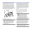
Stacking two of these loudspeakers one atop the other
and driving both with the same signal results in a different
radiation pattern. At common points on-axis, there is
constructive interference, and sound pressure increases by
6 dB relative to a single unit. At other points off-axis, path
length differences produce cancellation, resulting in a lower
sound pressure level. In fact, if you drive both units with
a sine wave, there will be points where the cancellation is
complete, which can be shown in an anechoic chamber.
This is destructive interference, sometimes referred to as
combing.
A typical line array comprises a line of loudspeakers
carefully spaced so that constructive interference occurs
on-axis of the array, and destructive interference (combing)
is aimed to the sides. While combing has traditionally been
considered undesirable, line arrays use combing to positive
effect: Without combing, there would be no directivity.
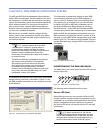
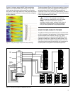
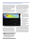
THE M2D LINE ARRAY
The M2D loudspeaker employs a unique combination
of drivers to enable you to optimize both coverage and
directivity in an M2D system. To achieve optimal results, it’s
critical to understand how these components work together.
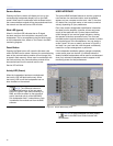
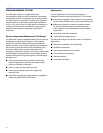
High Frequencies
For high frequencies, the M2D loudspeaker provides a
consistent beamwidth of coverage in both the vertical and
horizontal planes. In the horizontal pattern of the array, the
M2D loudspeaker’s horn works just as any wave guide does
to produce wide coverage; in the vertical, however, the
M2D loudspeaker’s REM technology provides very narrow
coverage in order to:
Minimize destructive interference between adjacent
elements
Maximize coupling to throw longer distances
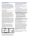
As more and more elements are arrayed in a vertical
column, they throw mid- and high-frequency energy more
effectively through coupling. The amount of energy can then
be controlled using the relative splay between the elements.
Gently curving a line array (no more than 7 degrees of
splay between cabinets) can aid in covering a broader
vertical area, while narrow angles provide a longer throw
and coverage that more closely matches that of the low
frequencies.
NOTE: Radically curving a line array
introduces problems. While a drastic angle
can spread high frequencies over a larger area, low
frequencies remain directional (the curvature change
is trivial at long wavelengths), resulting in uneven
coverage. In addition, a vertically narrow high-
frequency pattern combined with large angles can
produce hot spots and areas of poor high-frequency
coverage.
Mid to Low Frequencies
For the mid to low frequencies, array elements must be
coupled together to narrow their vertical coverage and
throw mid and low energy to the far eld. As frequencies get
lower and wavelengths get longer, the splay angle between
cabinets has little effect. The number of array elements,
however, is important: the more M2D loudspeakers used,
the narrower the vertical beamwidth becomes.
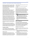
Adjusting Line Array Coverage
Regardless of the needs of your system design, ne-tuning
coverage for a single M2D array will be dependent on three
factors:
Number of Array Elements. Determining the number
of elements to use is critical: Too few elements can
drastically affect the uniformity of coverage of both SPL
and frequency.
Vertical Splay Angles. Changing the splay angles
between array elements has a signicant impact on
vertical coverage, with the result that narrower vertical
splay angles produce a higher Q vertical beamwidth,
while wider splay lowers the Q at high frequencies.
CHAPTER 4: LINE ARRAYS AND SYSTEM INTEGRATION