


16
CHAPTER 3
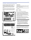
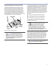
Service Button
Pressing the Service button will display an icon on the
corresponding loudspeaker display icon on the RMS
screen. When used in combination with the Reset button,
the communications module will be decommissioned from
the network and the red Service LED will blink.
Wink LED (green)
When lit, the Wink LED indicates that an ID signal
has been sent from the host station computer to the
loudspeaker. This is accomplished using the Wink button
on the loudspeaker Icon, Meter or Text views in the RMS
monitoring program.
Reset Button
Pressing the Reset button will cause the rmware code
within the RMS card to reboot. However, the commissioning
state of the communications module will not change (this
is stored in ash memory). When used in combination with
the Service button, the communications module will be
decommissioned from the network and the red
Service LED will blink.
Acivity LED (Green)
When the loudspeaker has been commissioned
the Activity LED will ash continuously. When
the Activity LED is unlit the loudspeaker has not
been installed on the network.
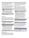
NOTE: The LEDs and buttons on
the RMS section of the user panel
shown in Figure 3.3 are used exclusively by
RMS, and have no effect on the acoustical
and/or electrical activity of the M2D/M2D-
Sub loudspeaker itself – unless Mute or Solo
is enabled at the module and from the RMS
software.
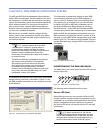
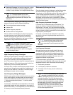
USER INTERFACE
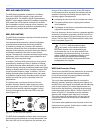
The optional RMS software features an intuitive, graphical
user interface. As mentioned earlier, each loudspeaker
appears on your computer monitor as a “view” in the form
of a status icon, bar graph meter, or text meter (numerical
values), depending on your preferences.
Each view contains loudspeaker identication information
and data from the amplier, controller, drivers and power
supply of that particular unit. System status conditions
cause changes in icon and bar graph indicators, alerting
the operator to faults or excessive levels. The views are
moveable and are typically arranged on the screen to reect
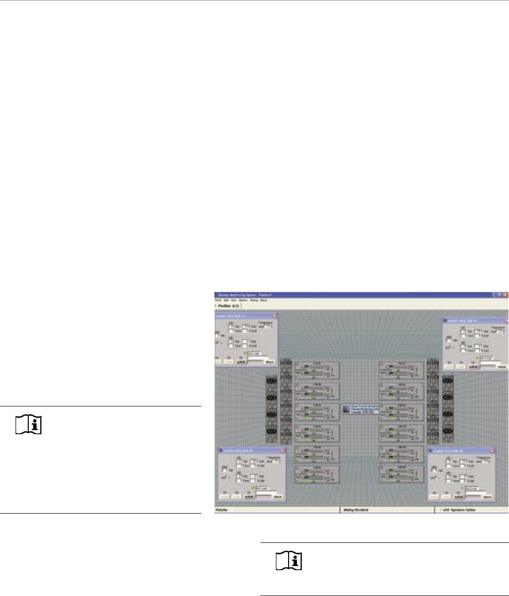
the physical layout of the loudspeakers. You can design a
screen “panel” of icons or meters, as shown in Figure 3.4,
and save it on your hard disk, with the panel conveniently
named for a unique arrangement or performer.
If the loudspeaker installation pattern changes completely,
a new screen panel can be built. If a different subset of
already installed loudspeakers will be used for a subsequent
show, only selected loudspeakers need to appear on the
monitoring screen for that performance.
NOTE: For more information on RMS, please
refer to the RMS User Guide included with
the software.
Figure 3.4. Sample RMS display panel