


18
CHAPTER 4
19
CHAPTER 4
Horizontal Coverage. Horizontal coverage for a single
array can be considered constant regardless of the
number of array elements or the angles between them.
TIP: The angle between two or more
line arrays can also be changed to meet
additional design requirements (for example, wall
reections).
Given these factors, designing and deploying a line array
system will typically have the following objectives:
Even horizontal and vertical coverage
Uniform SPL
Uniform frequency response
Sufcient SPL for the application
With two different technologies (low-frequency line array
and high-frequency wave guide) built into each M2D
cabinet, achieving these goals becomes a multi-step
process, with different strategies for the lower and higher
frequencies for long throws and short throws.
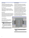
NOTE: THE Meyer Sound MAPP Online
prediction program, covered in greater detail
later in Chapter 5, “System Design and Integration
Tools,” enables you to make accurate and
comprehensive predictions for optimal coverage(s)
during the design phase.
High-Frequency Design Strategies
Planning for high-frequency coverage is a matter of ne-
tuning the splay angles between cabinets while keeping
an eye on the number of far-throwing elements in the
array. The number of elements does not necessarily have a
signicant impact on SPL at high frequencies (it will at low
frequencies), but can profoundly affect throw.
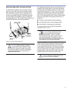
For the far eld, a smaller mechanical splay angle achieves
superior throw through better coupling to compensate for
energy lost over distance. In the near- to mid-eld, larger
splay angles increase vertical coverage.
Low-Frequency Design Strategies
While the wave guide provides isolated control over various
mid to high-frequency coverage areas, the low-frequency
section of an M2D line array still requires mutual coupling
— with equal amplitude and phase — to achieve better
directionality.
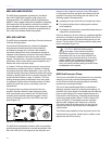
Low frequency directionality is less dependant on the array’s
relative splay angles and more dependent on the number of
elements of the array. At low frequencies, the more elements
in the array, the more directional the array becomes.
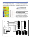
Electronically Driving the Array
Once the design (number of elements, vertical splay angles
and horizontal splay angles between arrays) has been
determined, you can effectively optimize the array by driving
it with multiple equalization channels, or zones. Typically
arrays are divided in two or three zones depending on
the design and size of the array; to optimize EQ, different
strategies are used for the low and high frequencies for long
throws and short throws.
High-Frequency Equalization Strategies
For the far eld, air absorption plays a critical role. The
farther the distance, the greater the attenuation at high
frequencies. In this zone, very high frequencies generally
need a boost to compensate for energy lost over distance;
the gain needed is usually proportional to the distance and
high-frequency air absorption.
In the near- to mid-eld, the air absorption is not nearly
as critical; in this zone, high frequencies need little or no
additional gain.
TIP: If your M2D array uses a third zone for
short throws, high frequencies there may
need to be attenuated to avoid excess levels in the
near eld.
Low-Frequency Strategies
Although the array can (and usually should) be zoned
for implementing different equalization curves for high
frequencies, similar or identical equalization should be
maintained in all the low-frequency lters. Different low-
frequency equalization settings in the same array will
degrade the desired coupling effect.
For the same reason, gain tapering is not recommended
for line arrays, since adjusting various zones with an overall
amplitude control for each zone results in the following:
1. Directionality decreases.
2. Low-frequency headroom decreases.
3. The length of the line array column is effectively
shortened.
TIP: The LD-3 compensating line driver was
designed to implement both low- and high-
frequency strategies with its array and atmospheric
correction functions. The LD-3 line driver’s array
correction function compensates for low-frequency
build-up, while the atmospheric controls correct for
the attenuation of sound in air at high-frequencies.
For more information on the LD-3 line driver’s
atmospheric and array correction features, please
refer to the LD-3 datasheet, operating instructions
or visit www.meyersound.com.