


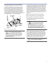


12
CHAPTER 2
13
CHAPTER 2
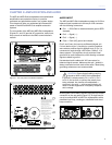
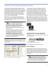
M2D-SUB AMPLIFICATION
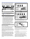
The M2D-Sub loudspeaker is powered by the Meyer
Sound HP-2/M2D-Sub amplier, a high-power two-
channel amplier. The amplier utilizes complementary
MOSFET output stages (class AB/H) capable of delivering
2250 watts total. All the specic functions for the M2D-
Sub loudspeaker such as crossover points, frequency and
phase response, and driver protection are determined by
the control card installed inside the amplier.
M2D-SUB LIMITING
The M2D-Sub loudspeaker uses Meyer Sound’s advanced
TruPower limiting system.
Conventional limiters assume a constant loudspeaker
impedance and therefore set the limiting threshold
by measuring voltage only. However, this method is
inaccurate, because the driver's impedance changes in
response to the frequency content of the source material
and thermal variations in the driver's voice coil and
magnet. Consequently, conventional limiters begin limiting
prematurely, which under-utilizes system headroom and
lessens the driver's dynamic range.
In contrast, TruPower limiting accounts for varying driver
impedance by measuring current, in addition to voltage,
to compute the actual power dissipation in the voice coil.
TruPower limiting improves performance before and during
limiting by allowing each driver to produce maximum SPL
across its entire frequency range. In addition, TruPower
limiting eliminates power compression when the system
is operated at high levels for extended periods, and also
extends the driver life cycle by controlling voice coil
temperatures.
The actual power is monitored for each of the two
amplier channels. When the safe continuous power
level is exceeded in any channel, the TruPower limiter
controlling both amplier channels engages. Limiting
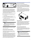
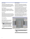
activity is indicated by the Sub Limit LED on the user
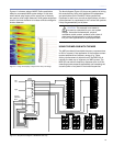
panel (Figure 2.5).
THISAPPARATUSMUSTBEEARTHED.
REFERSERVICINGTOQUALIFIEDPERSONNEL.
UNDREPARATURNURDURCHELEKTROF�CHKRAFTE
95-125V~ 208-235V~
INTERNESNESONTAUTORISEESQU'AU
Auto-VoltageSelect
PERSONNELTECHNIQUEQUALIFI…
NOOPERATORSERVICEABLEPARTSINSIDE.
Turnon165V~ Turnoff264V~
Turnon85V~ Turnoff134V~
OperationalVoltageRange:
1400WRMSMAX1400WRMSMAX
50-60Hz 50-60Hz
ENTRETIENETREPARATIONS
Wi
n
k
S
e
r
v
i
c
e
A
c
tivity
R
e
se
t
U.K.WARNING:
ATTENTION:
THIS PRODUCT MUST BEGROUNDED
Thissurfacemayreachhightempuratureswhiteinuse.
Toensureproperoperation,allowatleast6inches
AUTHORIZADOAPERSONALT…CNICOCALIFICO
Toreducetheriskofelectricshockdonotremovecover.
GEH�USENICHTOFFENEWARTUNG
ACCESOINTERNOSOLO
Toreducetheriskoffireorelectricshock
Referservicingtoqualifiedpersonnel.
Nooperatororserviceablepartsinside.
donotexposethisappliancetorainormoisture.
clearancefromthissurfaceandadequateventilation.
ATENCI”N:
ACHTUNG:
WARNINGS:
MeyerSound,Berkeley,CAUSA
Figure 2.5. The M2D-Sub’s LED indicators
The M2D-Sub loudspeaker performs within its acoustical
specications and operates at a normal temperature if the
Sub Limit LED is lit for no longer than two seconds, and
then go off for at least one second. If the LED remains
on for longer than three seconds, this indicates that the
amplier is incurring hard limiting that can result in the
following negative consequences:
Increasing the input level will not increase the volume.
The system distorts due to clipping and nonlinear
driver operation.
The lifespan of the drivers is reduced because they are
subjected to excessive heat
Each low-frequency driver is driven by a separate amplier
channel but is routed to one limiter; the Sub Limit LED on
the user panel indicates TruPower limiting activity for the
drivers. The Sub Limit LED indicates when the safe power
level is exceeded (Figure 2.5).
CAUTION: While the limiters protect
the system under overload conditions
and exhibit smooth sonic characteristics; we
recommend that you do not drive the M2D-Sub
loudspeaker into continuous limiting. If an entire
system of M2D-Sub loudspeakers begins to limit
before reaching the required sound pressure
level, you should consider adding more M2D-Sub
loudspeakers to the system.
M2D-Sub Excursion Clamp
The drivers in the M2D-Sub are protected by an excursion
clamping circuit that provides instantaneous braking
for the drivers without the pumping effects commonly
produced by compressor/limiters.
The circuit uses sophisticated filters to minimize the
distortion normally caused by clamping and clipping. As
the M2D-Sub’s input signal is increased past the clamping
point at each frequency, the output signal remains at a
fixed level for that frequency, protecting the drivers and
minimizing negative sonic effects. The Exc.Clamp LED,
shown in Figure 2.5, illuminates when the maximum
allowed peak voltage at each frequency is reached.
This circuit works for all frequencies, not just very low
frequencies where the drivers are more vulnerable to
overexcursion.
The limiters cease operation when the power level in the
channel returns to normal. Limiters have no effect on the
signal when the LED is inactive