


18
CHAPTER 4
19
CHAPTER 4
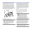
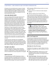
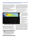
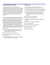
Figures 4.1 shows a series of MAPP Online predictions
based on an example M2D system design. In this case,
small vertical splay angles on the upper part of the array
are used to cover longer distances, while greater angles are
used in the lower elements to increase vertical coverage for
shorter distances.
Figure 4.1: Using vertical splay to adjust a line array’s coverage
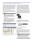
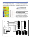
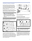
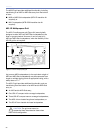
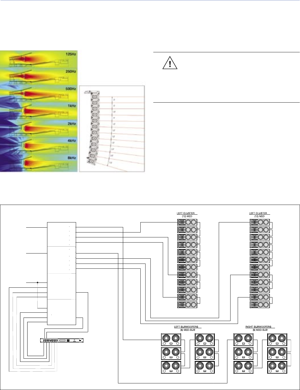
The block diagram (Figure 4.2) shows one method of driving
this example array, along with additional ll loudspeakers
and subwoofers (not in the MAPP Online predictions).
Equalizers for each zone, as well as digital delays, provide a
time adjustment to compensate for the various sub-systems
if they are geometrically out of plane.
CAUTION: This example is not meant to
be used as a template for your own system
designs. Acoustical characteristics, physical
constraints, audio content, audience, and a slew of
other factors should always be uniquely weighed
into your own applications on a per-project basis.
USING THE M2D-SUB WITH THE M2D
The M2D provides full bandwidth frequency response down
to 60 Hz, however, if the application or the program content
requires additional low-frequency energy (e.g., clubs,
discos, reinforcement of popular music), the M2D-Sub is
naturally the best way to augment your M2D system. The
M2D-Sub can achieve frequency response down to 30 Hz,
extending system response appreciably and increasing the
acoustic power of a system in the lowest frequencies.
Figure 4.2: Sample block diagram of M2D/M2D-Sub array
DigitalDelay
2Inx6Out
Digital Delay/EQ
LD-3
ChannelA
IN SUBOUT
CH1OUT
CH2OUT
CH3OUT
ChannelB
IN SUBOUT
CH1OUT
CH2OUT
CH3OUT
ChannelA
INSERTS SENDS
INSUB OUT
FullRange
INCH1 OUT
PostArray
INCH2 OUT
PostArray
INCH3 PostHPF
ChannelB
INSERTS SENDS
INSUB OUT
FullRange
INCH1 OUT
PostArray
INCH2 OUT
PostArray
INCH3 PostHPF
Main
Left
Right
Optional
Subwoofer
Mono