


10
CHAPTER 2
11
CHAPTER 2
When driving multiple loudspeakers in an array, make
certain that the source device can drive the total load
impedance presented by the paralleled input circuit of the
array. The audio source must be capable of producing
a minimum of 20 dB volts (10 volts rms into 600 ohms)
in order to produce the maximum peak SPL over the
operating bandwidth of the loudspeaker.
To avoid distortion from the source, make sure the source
equipment provides an adequate drive circuit design
for the total paralleled load impedance presented by
the array. The input impedance for a single loudspeaker
is 10 kOhms: if n represents the number of M2D/M2D-
Sub loudspeakers in an array, paralleling the inputs of n
loudspeakers will produce a balanced input load of 10
kOhms divided by n.
NOTE: Most source equipment is safe for
driving loads no smaller than 10 times the
source’s output impedance.
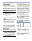
For example, cascading an array of 10 units consisting of
M2D and/or M2D-Sub loudspeakers produces an input
impedance of 1000 ohms (10 kOhms divided by 10). The
source equipment should have an output impedance of
100 ohms or less. This is also true when connecting M2D/
M2D-Subs in parallel (loop out) with other self-powered
Meyer Sound loudspeakers.
CAUTION: Shorting an input connector pin
to the case can form a ground loop and
cause hum.
TIP: If abnormal noises such as hiss and
popping are produced by the loudspeaker,
disconnect the audio cable from the loudspeaker.
If the noise stops, then most likely the problem
is not with the loudspeaker. Check the audio
cable, source, and AC power for the source of the
problem.
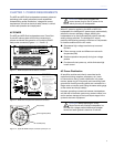
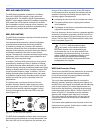
M2D INTERCONNECTIONS
For the low and low-mid frequencies, the M2D utilizes
two 4-ohm, 10-inch cone drivers featuring lightweight
neodymium magnet structures.
A complex passive network connected between the
amplier and the drivers is used to ensure smooth
response in the critical midrange. At the lowest
frequencies, the two high-power, back-vented cone
drivers combine to reproduce coherent low frequencies.
In the mid frequencies, the passive network feeds only
one of the two drivers while correcting the phase shift at
low frequencies for proper addition with the other driver.
This technique eliminates interference between the high-
frequency and low-frequency drivers that would otherwise
occur near the crossover frequency, and maintains optimal
polar and frequency response characteristics.
To reproduce high frequencies, the M2D employs Meyer
Sound's patented REM ribbon emulation manifold to
couple a constant-directivity horn to a compression driver
with a 1.5-inch exit (4-inch diaphragm). REM controls the
output of the driver and introduces it to the horn throat
within a three-inch path length, dramatically minimizing
distortion. This unique horn design produces a coherent
wave front that is characteristic of, but much more
powerful than, a large ribbon driver.
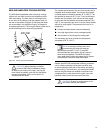
CAUTION: All Meyer Sound loudspeakers
are shipped with the drivers in correct
alignment. However, if a driver needs to be
replaced, make sure the replacement is reinstalled
with the correct polarity. Incorrect driver polarity
impairs the system performance and may damage
the drivers.
M2D AMPLIFICATION
All three drivers in the M2D are powered by a two-channel
proprietary Meyer Sound UX-M2D amplier utilizing
complementary MOSFET output stages (class AB/bridged)
capable of delivering 700 watts total. The amplier
employs electronic crossover, phase, and frequency
response correction lters – as well as protection circuitry
– to process the audio signal. All the specic functions
for the M2D are determined by the control card installed
inside the amplier; one channel of the amplier drives the
low and low-mid section of the M2D through the passive
network while the other channel drives the high frequency
section.
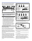
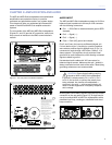
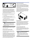
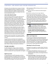
M2D LIMITING
Each channel of the amplier has limiters that prevent
driver over-excursion and regulate the temperature of the
voice coil. Limiter activity for the high and low channels is
indicated by two yellow Limit LEDs on the rear panel (the
high-frequency limit LED is the top and the low-frequency
limit LED is the bottom, as shown in Figure 2.4).