


4
CHAPTER 1
5
CHAPTER 1
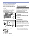
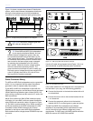
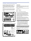
Figure 1.4 shows a sample three-phase AC distribution
system, with the load between loudspeakers distributed
among the three phases and all of the loudspeakers
connected to common neutral and earth ground points.
Figure 1.4. A sample AC power distribution block diagram
CAUTION: Continuous voltages higher than
265 volts can damage the unit.
TIP: Since M2D and M2D-Sub loudspeakers
do not require a dedicated Neutral, and can
tolerate elevated voltages from ground, they can
be connected between line-line terminals in a 120
volts 3-phase Wye system. This results in 208 volts
AC betweens lines (nominal) and will therefore draw
less current for the same output power compared
to operating the loudspeaker from 120 volts AC
(line- neutral). Make sure that the voltage remains
within the recommend operating window. The
ground terminal must always be used for safety and
the line-to-ground voltage should never exceed 250
volts AC (typically there will be 120 volts AC from
line to ground in the above example).
Power Connector Wiring
The M2D and M2D-Sub loudspeakers require a grounded
outlet. It is very important that the system be properly
grounded in order to operate safely and properly.
If your M2D or M2D-Sub loudspeaker is tted with the
VEAM multipin connector, see the Meyer Sound document
VEAM Cable Wiring Reference (part number 06.033.113)
for the wiring conventions and pin-outs for AC, audio, and
RMS connections.
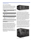
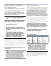
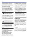
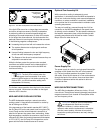
Meyer Sound offers two VIMs (VEAM interface module)
for simple, all-in-one RMS, audio and power distribution
using VEAM multi-conductor cables. As shown in Figure
1.5, the VIM-4 module consists of four VEAM connectors
and 8-amp breakers for the M2D loudspeaker; the VIM-
3 consists of three VEAM connectors and 10-amp
breakers for the higher-current M2D-Sub loudspeaker.
Both modules feature a single-phase IEC309 32-amp rear
connector.
Figure 1.5. VIM-3 (top) and VIM-4 (bottom) modules
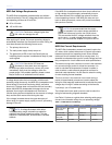
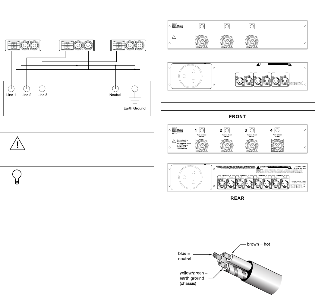
Use the AC cable wiring diagram below (Figure 1.6) to cre-
ate international or special-purpose power connectors:
Figure 1.6. AC cable color code
If the colors referred to in the diagrams don’t correspond to
the terminals in your plug, use the following guidelines:
Connect the blue wire to the terminal marked with an N
or colored black.
Connect the brown wire to the terminal marked with an
L or colored red.
Connect the green and yellow wire to the terminal
marked with an E or colored green or green and yellow.
The M2D and M2D-Sub loudspeakers use different
ampliers to accommodate power requirements for their
drivers, hence they have different voltage and current
requirements. The M2D uses a UX-M2D amplier while the
M2D-Sub uses an HP-2/M2D-Sub amplier.