51 of 66
7.0 User Interface Operation
7.4 Page user interface operation
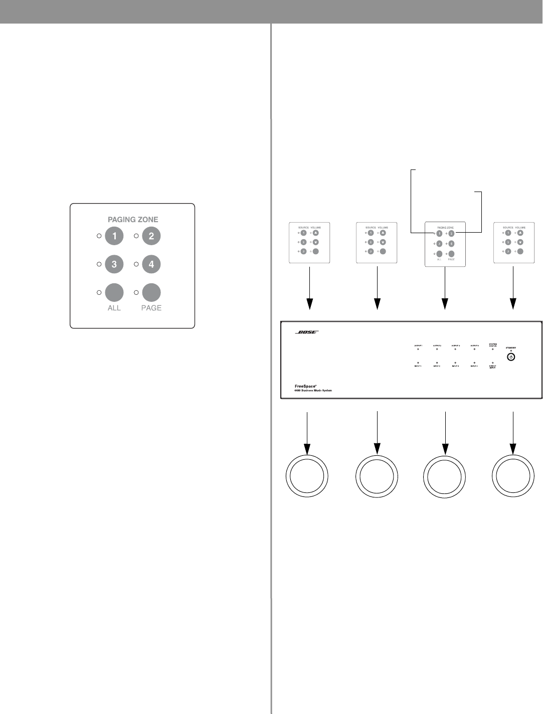
The Page user interface provides keys to select single paging
zones, all paging zones and initiate a page.
Paging zones are not the same as output zones. After assigning
the PAGE source to the output zones and choosing the appropri-
ate settings in the Page Setup control pane, flashing the hard-
ware maps the paging zone buttons accordingly.
When mapped, the paging zone 1 button will select the lowest
numbered output ZONE to which the PAGE source is assigned.
The paging zone 2 button will select the next lowest numbered
output ZONE to which the PAGE source is assigned, and so forth.
• Press 1, 2, 3 or 4 to select a paging zone. A green LED flashes
to indicate that the zone is selected for paging. After ending a
page the LED turns off.
• Press ALL to select all paging zones.
• Press PAGE to initiate a page in systems that do not use a PTT
(push-to-talk) microphone.
Page User Interface Example:
•The
PAGE
source is assigned to ZONE OUTPUT 1 and ZONE
OUTPUT 4.
• In the Page Setup control pane for ZONE 1 and ZONE 4:
Paging Type = Multi-zone
PAGE Control = Wall plate 3
• After flashing the hardware, the paging zone 1 button selects
ZONE OUTPUT 1 for paging, and the paging zone 2 button
selects ZONE OUTPUT 4 for paging.
Select paging
zone #2
Select paging
zone #4
Initiate a page
Select paging
zone #1
Select paging
zone #3
Select all
paging zones
Page User Interface
WALL PLATE WALL PLATE WALL PLATE WALL PLATE
ZONE OUTPUT ZONE OUTPUT 2 ZONE OUTPUT ZONE OUTPUT 4
AVM
User Interface
Page
User Inter-
AVM
User Inter-
AVM
User Inter-
Paging zone 1 Paging zone 2
ZONE 1
Loud-
speakers
ZONE 2
Loud-
speakers
ZONE 3
Loud-
speakers
ZONE 4
Loud-
speakers
Mapped to select
ZONE 1
Mapped to select
ZONE 4
MUTE /
AUTO VOL
MUTE /
AUTO VOL
MUTE /
AUTO VOL
