


16 of 66
4.0 Hardware Installation
4.6 Installing accessories
Installer’s Note: Disconnect the FreeSpace 4400 system
from the AC (mains) power before making any input/output
connections.
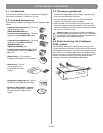
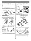
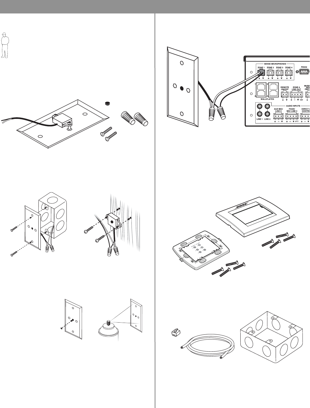
4.6.1 Sensing microphones
Required accessory:
FreeSpace
®
4400 System Auto Volume Mic Kit [PC042354 (U.S.),
PC042355 (Euro)]
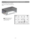
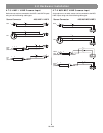
Microphone installation:
The wall plate-microphone assembly can be installed using a
single-gang junction box, or the microphone can be removed
from the wall plate and mounted directly on a flat surface.
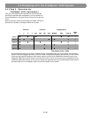
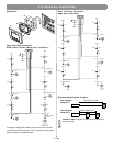
Recommended wire length:
Up to 2000 ft (610 m) max., 24 AWG (0.2 mm
2
) shielded twisted
pair (shield tied to minus at FreeSpace 4400, floated at sense
mic).
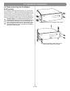
Painting:
Before painting the wall
plate, install the sup
-
plied temporary plug
over the microphone
opening. Remove the
plug when finished.
Mounting locations:
For mounting instructions, see “Mounting guidelines for sensing
microphones” on page 4.
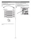
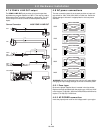
4.6.2 Auto volume microphone inputs
Connect each sensing microphone to the SENSE MICRO-
PHONES jacks on the FreeSpace 4400 rear panel.
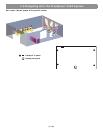
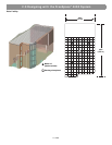
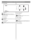
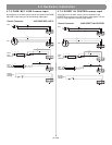
4.6.3 User interfaces
Required accessory: FreeSpace
®
4400 System AVM 1-Zone
User Interface [PC042351] or
FreeSpace
®
4400 System AVM 2-Zone
User Interface [PC042352] or
FreeSpace
®
4400 System Page User
Interface [PC042353]
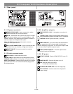
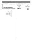
Required additional equipment (not supplied):
*FreeSpace
®
4400 System AVM 2-Zone User Interface requires
the use of two (2) RJ45 connectors and two (2) Cat 5 cables.
Wall plate-microphone
assembly
(2) #6-32 (3 mm) screws
(2) Wire nuts
Paint plug
Junction box installation Surface-mounted mic
M
U
T
E
/
AU
TO
V
O
L
A
Wall plate
B
Keypad
C
RJ45
connector*
D
Cat 5 cable*
(with 4 twisted pairs)
E
Double-gang
junction box