


MP3 NG: A Next Generation Consumer Platform
XAPP169 (v1.0) November 24, 1999 www.xilinx.com 23
1-800-255-7778
R
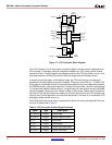
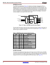
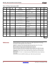
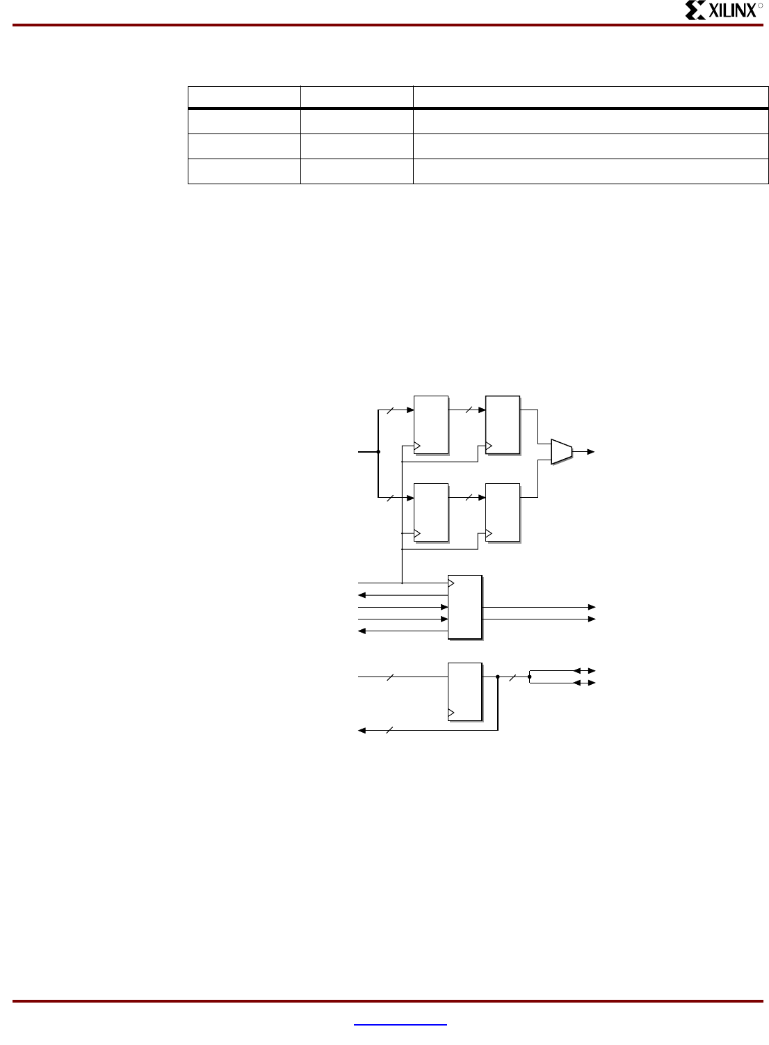
Audio DAC Interface
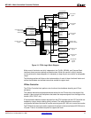
The interface for the CS4343 consists of two separate functional blocks, one for each of the
serial interfaces that are required to support this device. Figure 22 shows a block diagram of
this interface.
The control port interface is implemented as a 2-bit I/O port that is manipulated by software in
order to implement the I
2
C protocol used for accessing the control and status registers in the
DAC. This approach uses minimal device resources and is practical due to the low data rate of
this port and its infrequent use.
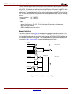
When the system is in operation, the serial audio port is in use most of the time. Therefore,
dedicated hardware is provided for implementing the transfer protocol and for delivering an
uninterrupted audio stream. This hardware consists of two, 4-word FIFOs, one for each audio
channel and a state machine to manage the FIFOs and sequence the interface signals.
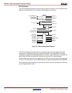
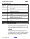
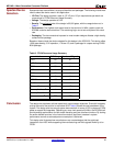
Table 5: Table 5 IRDA Transceiver Interface Signal Summary
Signal Type Description
IR_TXD Output Transmit data
IR_RXD Input Receive data
IR_SD Output Shut down signal, puts transceiver into low power mode
D_IN[31:0]
32
FIFO
Shift
Register
32
DQ
DQ
DAC_MCLK
DAC_LRCK
State
Machine
SYS_CLK
INT_N
RD_N
ACK_N
WR_N
32
FIFO
Shift
Register
32
DQ
DQ
MUX
DAC_SDATA
Register
DQ
D_IN[31:0]
32
2
DAC_SCL
DAC_SDA
D_OUT[31:0]
32
Figure 22: Audio DAC Interface Block Diagram