


MM-012099-001, Rev. B
29
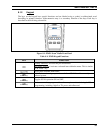
Figure 7-7: Full Cycle Battery Charge Indicator
The battery charge indicators illustrate approximate level only, based on battery voltage. Refer to Figure
7-7.
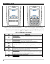
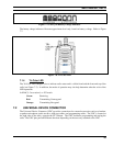
Figure 7-8: Tri-Color LED
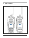
7.1.4 Tri-Color LED
The Tri-Color LED changes color to indicate radio status and is visible from both the front and top of the
radio (see Figure 7-2). In addition, the mode of operation may
also help determine what the color of the
LED represents.
In EDACS, Conventional, or P25 modes
Green: Receiving
Red: Transmitting Unencrypted
Orange: Transmitting Encrypted
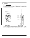
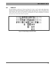
7.2 UNIVERSAL DEVICE CONNECTOR
The Universal Device Connector (UDC) provides connections for external accessories such as a headset,
a speaker-microphone, audio test box, audio test cables, and programming cables. The UDC is located on
the right side of the radio, opposite the PTT Button. The UDC facilitates programming and testing the
radio. The UDC pins perform different functions depending on the accessory attached to the UDC.