


4
Screw in the feet with locking ring
attached, with either the spikes or rubber
tips outermost, according to the type of
floor surface. Leave the tips of the feet
protruding beyond the inner packing
pieces for clearance when the speaker is
upright.
After rolling the cabinet onto its feet and
lifting off the carton, remove the inner
packing and adjust the feet as described
in section 3.3
f Continue to section 3.3.
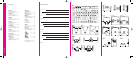
3.3 ADJUSTING THE FEET
The threaded bosses that hold the feet
have a large conical shape on one side
of the flange. For maximum height, fit the
bosses with the conical shape towards
the floor. (figure 21) For minimum height,
have them pointing into the speaker.
(figure 22)
Screw in the feet close to where you
think the final adjustment will be, with the
spikes or the rubber ends outermost as
appropriate to the floor surface. If you do
not intend to tilt the speakers, orient the
bosses with the cones inwards and leave
just enough thread exposed to fit the
locking rings. Fit, but do not tighten the
locking rings.
Stand the speaker upright and adjust the
feet using the metal bar provided to give
the amount of tilt required and to take up
any rocking. (figure 23)
Finally, tighten the locking ring against
the boss, again using the metal bar.
(figure 24)
f Go to section 4.
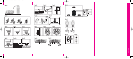
3.4 803D/803S/804S
For best performance, screw the
adjustable feet into the threaded inserts
in the base of the speaker as appropriate
– spikes for carpets or clear rubber for
wooden and other vulnerable floors.
(figure 25)
Lay the speaker down on its side (to
avoid possible damage to terminals or
drive unit diaphragms). Remove rings
and other jewellery to avoid scratching
the surfaces and provide a soft surface
such as a piece of carpet that the
speaker can lie on.
Screw the lock nuts fully onto the feet
and the feet fully into the base.
(figure 25)
Stand the speaker upright and adjust the
feet to take up any r
ocking.
Finally
, tighten the locking rings against
the threaded inserts. (figure 26)
f Go to section 4.
3.5
805S/HTM2D/HTM3S/HTM4S
These systems should be mounted on a
firm shelf or stand that allows the sound
to be properly directed to the listeners.
For the 805S, we recommend the use of
the FS-N805 stand that supports the
speaker at the correct listening height.
For the HTM2D, HTM3S and HTM4S,
the FS-NHTM stand supports these
centre speakers low down so that the
top of the speaker is no higher than
60cm (2 ft) from the floor, commensurate
with positioning them below a large
screen. The stand allows the speaker to
be tilted back by 0º, 4º or 8º.
Follow the instructions supplied with the
stand in each case.
When mounting the speakers on a
bookshelf, stick the 4 self-adhesive
rubber feet to the base of the speaker.
(figure 27)
f Go to section 4.
3.6 SCMS
The speaker is designed to be fixed to a
wall and is supplied with a bracket that
allows adjustment of both horizontal and
vertical angles. (figure 29) The bracket
should be fixed to the wall using screws
in the range 5mm to 6mm diameter
(No.10 to No.12). The screw length
should be chosen to give a minimum of
25mm (1 in) engaged thread. (figure 28)
Hold the template provided against the
wall in the desired position and use a
spirit level to line it up properly. The
outside dimensions of the template
correspond to the rear of the cabinet.
Note especially that the centre of the wall
plate does not coincide with the centre
line of the speaker.
Mark the fixing holes on the wall and drill
and plug the wall.
Ensure that the screw length and
wall plug security are sufficient to
hold the weight of the speaker. When
fixing to drywall construction, try to
arrange for the screws to go into a
stud. B&W can accept no liability for
any failure of wall or ceiling fixings.
Screw the wall plate D to the wall and
test the firmness.
Part screw two of the supplied machine
screws into the upper two threaded
inserts in the back of the cabinet.
Offer the speaker up to the speaker plate
E, locating the two scr
ew projecting from
the back of the speaker into the slots at
the top of the plate.
Fit the remaining two machine screws
thr
ough the plate E into the lower
threaded inserts in the cabinet and
tighten all four.
Set the vertical angle of the speaker by
adjusting screw B.
Fully tighten screw A.
Adjust screws C so that the friction of
the three vertical hinges allows you to
adjust the bracket but hold it in place
once set.
Connect the speakers as described in
section 4 before continuing.
Set the required horizontal angle and
push the speaker back to the wall, but
leave a little clearance to avoid rattles.
f Go to section 4.
3.7 DS8S
The speakers may be fixed to a wall or
ceiling using screws in the range 5mm to
6mm diameter (No.10 to No.12).
On the back of the cabinet are three wall
plates. The screw head should be
inserted into the round part of the
aperture and slid fully along one of the
slots. The slots are sprung loaded to
prevent the speaker being readily
knocked out of position. The screw
length should be chosen to give a
minimum of 25mm (1 in) engaged thread.
(figure 28)
Ensure, especially when fixing to drywall
panels, that the screw length and wall
plug security are sufficient to hold the
weight of the speaker. B&W can accept
no liability for any failure of wall or ceiling
fixings.
Use the template provided to mark the
screw positions. The outside dimensions
of the template correspond to the rear of
the cabinet.
Stick 4 of the clear self-adhesive rubber
pads to the rear panel of each speaker,
one close to each corner. These stop the
speaker vibrating against the surface and
help keep it in position. (figure 30)
Adjust the protrusion of the screws such
that the rubber pads are a friction slide
on the surface when the wall plates are
hooked over the screw heads. (figure 31)
Always check and ensure that:
• All the screws slide right to the
ends of the slots in the wall
plates.
• Screw protrusion is adjusted so
that the rubber pads provide
enough friction to prevent the
speakers sliding out of position.
f Go to section 4.