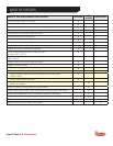
MSD 7R SHEARS
Page 6 Section 7 Rotator Maintenance
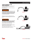
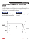
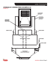
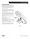
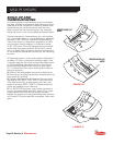
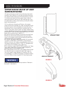
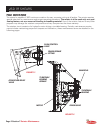
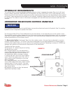
CROSSOVER RELIEF/FLOW CONTROL MANIFOLD continued
The crossover relief valve provides overload protection for the rotator. This is not intended to replace the cir-
cuit relief valve on the base machine. This valve has been preset at the factory and requires no adjustment;
it should not be tampered with. If a malfunction is suspected due to a lack of rotator performance, a pressure
check should be performed. Diagnostic fi ttings* are installed in the manifold to provide a means of checking
pressure. Contact the LaBounty Service Department for the procedure for performing this check.
* Diagnostic fi ttings require a Parker PD series coupler on gauge.
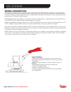
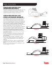
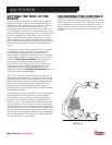
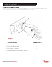
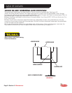
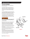
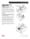
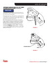
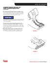
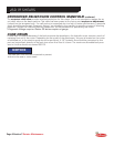
CASE DRAIN
A case drain is required because of the back pressure that develops in the hydraulic motor case as a result of
metering fl ow out of the motor. Depending on the model of the attachment, this port is located on the motor
or bulkhead out to the rotation group shroud or port block. A 1/4" hydraulic line should be connected to this
port and routed back directly to the tank via a return line fi lter of its own. The maximum allowable back pres-
sure in this line should not exceed 300 PSI.
The case drain line must be connected to prevent
failure to the case or motor seals.
NOTICE