MSD 7R SHEARS
Rotator Maintenance Section 7 Page 5
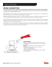
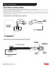
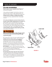
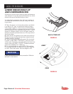
HYDRAULIC REQUIREMENTS
The rotating shear requires an auxiliary hydraulic circuit in order to operate the rotator. This circuit will need
to be a medium pressure (1350-2000 PSI / 93-138 BAR), low fl ow (4-10 GPM / 15-37 LPM) hydraulic circuit.
There are minimum and maximum pressure and fl ow requirements that may vary depending on the model of
the shear. These requirements are listed in the Hydraulic Installation Requirements sheet in the Parts Catalog
for the shear. The rotation motor on the shear is equipped with manifold mounted crossover relief and fl ow
controls.
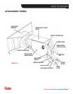
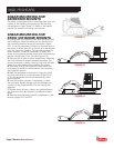
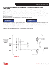
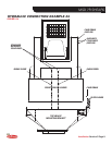
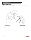
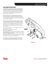
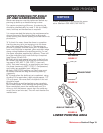
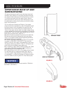
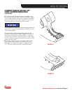
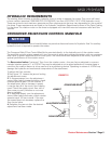
CROSSOVER RELIEF/FLOW CONTROL MANIFOLD
The crossover relief/fl ow control manifold does not provide a directional control of hydraulic fl uid. An auxiliary
hydraulic circuit is required to operate the rotator.
The Crossover Relief/ Flow Control Manifold is mounted directly to the hydraulic port of the rotation motor.
The manifold controls rotation speed with two fl ow control valves and overload protection with one crossover
relief valve to govern pressure at both motor ports. The valves have been adjusted at the factory to provide
optimal performance of the rotation motor.
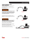
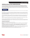
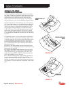
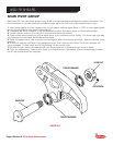
The fl ow control valves “meter-out” fl ow from the rotation motor—they are factory adjusted to a recom-
mended rotation speed of 1 to 2 RPM. They may be adjusted to suit a speed preference; however keep in
mind that the rotation feature is to be used only as a positioning device. Operating in excess of 4 RPM may
damage the hydraulic and mechanical components of the attachment.
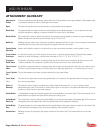
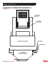
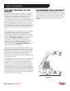
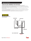
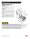
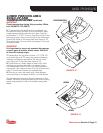
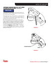
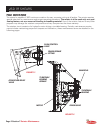
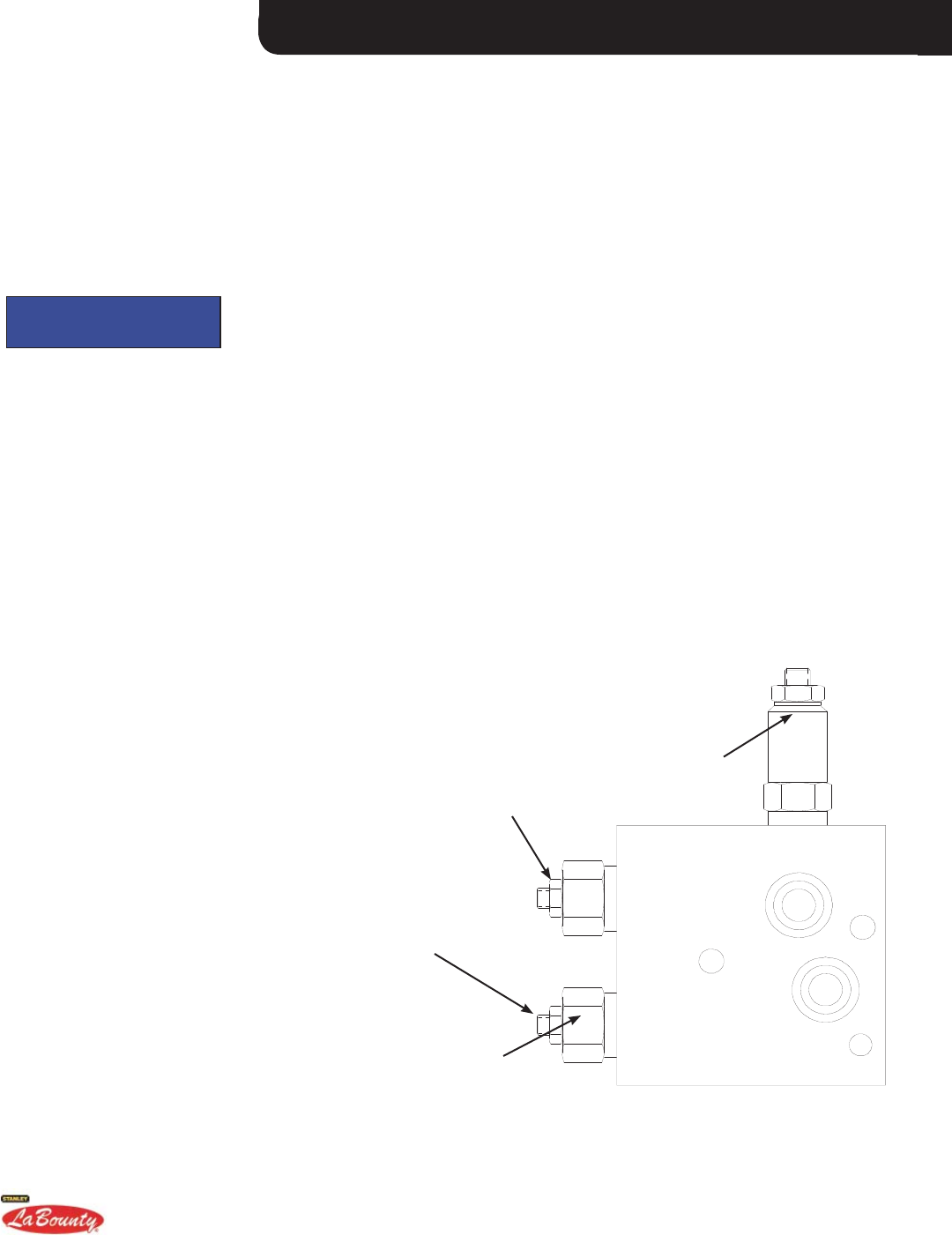
FIGURE 7-3
CROSSOVER RELIEF
NOTICE
JAMNUT
ADJUSTMENT SCREW
FLOW CONTROLS
To adjust the fl ow controls:
1. See fi gure 7-3. Loosen the jamnut locking
the adjustment screw.
2. To increase speed, turn the adjustment
screw (Allen head) counterclockwise; check
rotation speed at each 1/8 turn interval. If
the attachment fails to increase in speed,
it may be that all of the circuit fl ow is being
used. Check the supply circuit fl ow with a
fl ow meter to verify whether or not more
fl ow is available.
3. To decrease speed, turn the adjustment
screw (Allen head) clockwise; check rotation
speed at each 1/8 turn interval. If the rota-
tion speed does not decrease, replace the
fl ow control valve.
4. Retighten the jamnut after the desired
adjustment has been made.