MM23772, Rev. F
8
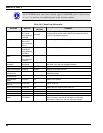
TABLE OF CONTENTS
Page
11.12 CONTRAST ADJUST .............................................................................................................112
11.13 DECLARE AN EMERGENCY ...............................................................................................112
11.14 LOCK/UNLOCK KEYPAD ....................................................................................................113
11.15 HIGH/LOW POWER ADJUSTMENT....................................................................................113
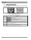
11.15.1 Using the Menu Button................................................................................................113
11.15.2 Using the Pre-Programmed Option Button..................................................................113
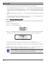
11.16 MENU ......................................................................................................................................113
11.16.1 Menu Item Selection Process.......................................................................................114
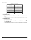
11.17 RECEIVE A CALL ..................................................................................................................116
11.18 TRANSMIT A CALL...............................................................................................................116
12 TECHNICAL ASSISTANCE............................................................................................................117
12.1 IMMERSIBLE P7200 ..............................................................................................................117
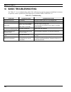
13 BASIC TROUBLESHOOTING........................................................................................................118
FIGURES
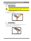
Figure 4-1: Removing the Battery Pack.........................................................................................................17
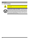
Figure 4-2: Attaching the Battery Pack..........................................................................................................17
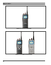
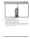
Figure 5-1: P7230 Select Model Radio..........................................................................................................20
Figure 5-2: P7250 and P5250 Scan Models...................................................................................................20
Figure 5-3: P7270 System Model ..................................................................................................................21
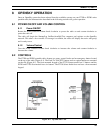
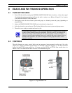
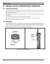
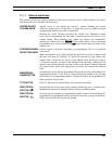
Figure 8-1: Top and Side View......................................................................................................................25
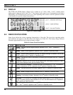
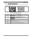
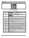
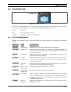
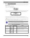
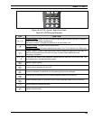
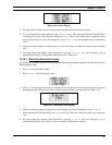
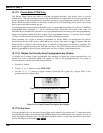
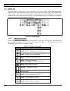
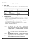
Figure 8-2: Radio Display..............................................................................................................................28
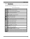
Figure 8-3: Tri-Color LED.............................................................................................................................29
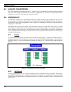
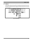
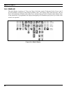
Figure 8-4: Personality Structure Example....................................................................................................30
Figure 9-1: Top and Side View......................................................................................................................57
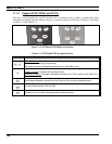
Figure 9-2: P7250 and P5250 Radio Front Panel...........................................................................................59
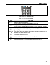
Figure 9-3: P7270 Radio Front Panel.............................................................................................................60
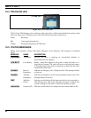
Figure 9-4: Radio Display..............................................................................................................................61
Figure 9-5: Tri-Color LED.............................................................................................................................63
Figure 9-6: Menu Display..............................................................................................................................68
Figure 9-7: Backlight Menu Display..............................................................................................................69
Figure 9-8: System Encryption Key Display .................................................................................................72
Figure 9-9: Group/Channel Encryption Key Display ....................................................................................72
Figure 9-10: Calls Received Lists..................................................................................................................78
Figure 9-11: WHC Individual Call Display...................................................................................................79
Figure 9-12: Calls Received and Personality Lists ........................................................................................80
Figure 10-1: Top and Side View....................................................................................................................86
Figure 10-2: P7250 and P5250 Radio Front Panel.........................................................................................88
Figure 10-3: P7270 “System” Radio Front Panel ..........................................................................................89
Figure 10-4: Radio Display............................................................................................................................90
Figure 10-5: Tri-Color LED...........................................................................................................................92
Figure 10-6: Menu Display............................................................................................................................97
Figure 10-7: Backlight Menu Display............................................................................................................97
Figure 10-8: System Encryption Key Display .............................................................................................100
Figure 10-9: Group/Channel Encryption Key Display ................................................................................100
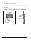
Figure 11-1: Top and Side View..................................................................................................................104
Figure 11-2: P7250 and P5250 Radio Front Panel.......................................................................................106