


Supply voltage: 12 V DC (10.8 V–16 V), test voltage 14.4 V, negative ground
Current consumption: Less than 2.0 A
Signal system: NTSC 1.0 Vp-p 75 ≠ RCA pin jack
Discs played: (1) DVD-VIDEO disc
5z (12 cm) single-sided, single-layer/double-layer
5z (12 cm) double-sided, single-layer/double-layer
3z (8 cm) single-sided, single-layer/double-layer
3z (8 cm) double-sided, single-layer/double-layer
(2) Compact disc (CD-DA, VIDEO CD, CD-ROM, CD-R, CD-RW)
5z (12 cm) disc
3z (8 cm) disc
Audio output level: 600 ≠ (2 ch 2.5 Vrms Max.)
Audio signal
output characteristics: (1) Frequency response: 20 Hz–20 kHz
(2) S/N ratio: 95 dB (IHF, A)
(3) Wow and Flutter: Below measurable limits
Dimensions (WaHaD): 7za1
15
/
16
za6
1
/
8
z (178a50a155 mm)
Weight: 3 lbs. 5 oz (1.5 kg)
Digital audio output:
†
DTS only works with optical outputs.
Above specifications comply with EIA standards.
Note:
≥ Specifications and design are subject to modification, without notice, due to improvements in technology.
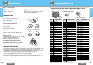
Disc Sound recording format Optical digital audio output from connector
DVD Dolby Digital Dolby Digital bitstream (1–5.1 ch)
DTS
†
DTS bitstream (1–5.1 ch) (The analog portion is not output.)
Linear PCM Linear PCM (2 ch)
(48 kHz 16/20/24 bit) (48 kHz sampling/16 bit only)
Video CD MPEG 1
MPEG 1 bitstream
Linear PCM
Linear PCM (2 ch) (44.1 kHz sampling/16 bit)
CD Linear PCM
Linear PCM (2 ch) (44.1 kHz sampling/16 bit)
DTS
†
DTS bitstream (1–5.1 ch) (The analog portion is not output.)
MP3 MP3
Linear PCM (2 ch) (32 kHz/44.1 kHz/48 kHz sampling/16 bit )
E
N
G
L
I
S
H
36
SpecificationsElectrical Connections (continued)
E
N
G
L
I
S
H
35
CX-DVP292U
45
CX-DVP292U
4444 45
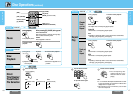
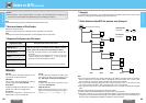
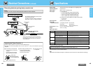
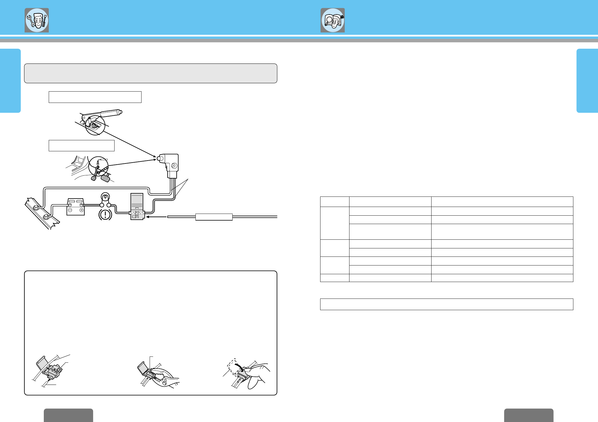
PARKING BRAKE
Chasiss
Battery
Brake lamp
5 Clamp connector
Parking brake
switch
Side brake (parking brake)
connection lead
(Blue/yellow stripe)
Of the 2 cords emerging from the parking brake switch,
connect the player’s parking brake cord to the one that is
not connected to the vehicle’s chassis while the brake is
in the released state.
Cords connected to
the vehicle.
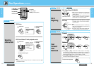
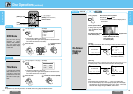
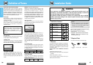
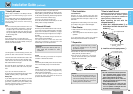
❐ Connecting side brake (parking brake) connection lead
Vehicle cord
Parking brake cord
Element
Cover
Push the end of the cord
in until it touches this part.
3 Close the cover until
it snaps shut.
1 Push the end of the side brake
cord into the hole on the clamp
connector.
Place the vehicle cord into the
groove in the clamp connector.
2 While making sure that the cords
do not slip out of the clamp
connector, press the element
down with a pair of pliers.
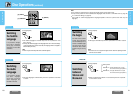
Caution:
≥ For safety, be sure to ask your nearest professional installer to do this connection.
The side brake (parking brake) switch position
varies with the car model.
For details on the exact location of the parking
brake switch in your car, contact your dealer.
“DTS” and “DTS Digital Out” are trademarks of Digital Theater Systems, Inc.
Side brake (parking brake)
Foot brake
Connecting the Clamp Connector
5
≥ Attach the clamp connector to the vehicle cord at a suitable position.
≥ Note that if the cord being clamped onto is too thin (0.3 mm
2
or less), the connection may not be
adequate.