


No.
6
4
E
N
G
L
I
S
H
32
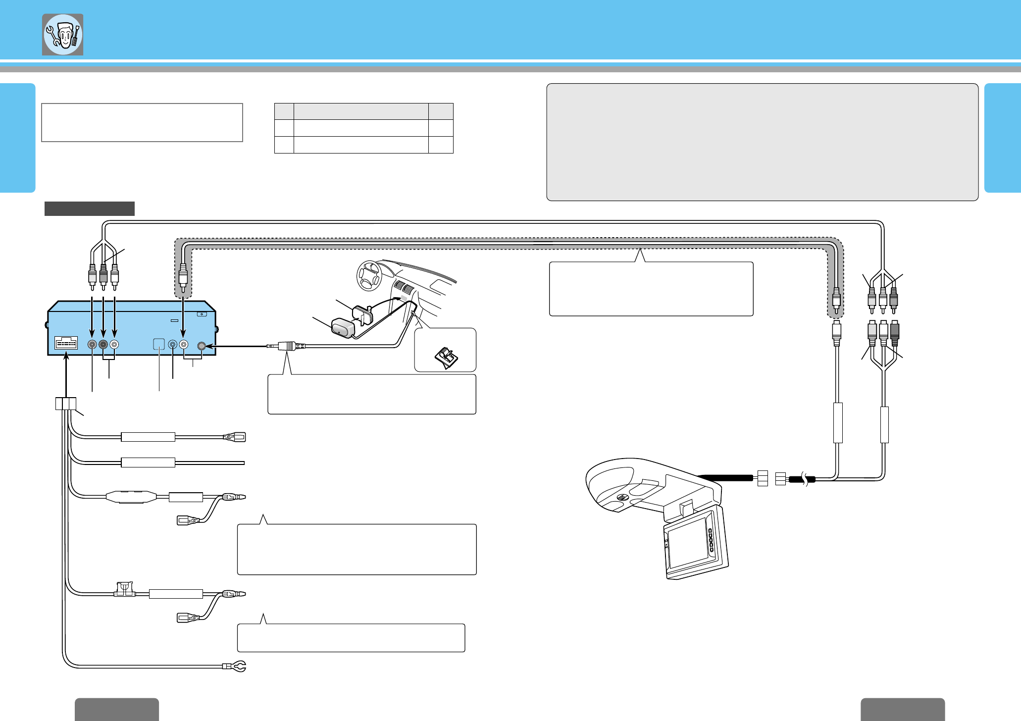
Electrical Connections
E
N
G
L
I
S
H
31
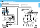
CX-DVP292U
41
CX-DVP292U
40
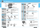
Item
40 41
BATTERY 5A
PARKING BRAKE
VIDEO-CONT
ACC
P
O
W
E
R
REMOTE-OUT
VTR1-IN
Resistor (1 k≠)
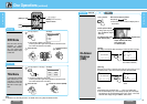
CX-DVP292U (Rear)
VIDEO OUT
AUDIO OUT
DIGITAL OUT
Not used.
REMOTE IN
L (White)
R (Red)
Video
(Yellow)
(Yellow)
RCA cord (option)
RCA cord (option)
Not used.
ACC power lead
To ACC power, +12 V DC.
Battery lead
To the battery, continuous +12 V DC.
Ground lead
To a clean, bare metallic part of car chassis.
(Black)
(Red)
(Green/yellow stripe)
(Blue/yellow stripe)
Fuse (5 A)
Side brake (parking brake) connection lead
(➡ page 44)
When connected to the lead colored in dark blue of the
Panasonic CD receiver or having an AUX-IN input terminal,
instead of connecting to the ACC power source, the power of
unit can be linked to that of receiver.
Connect the battery power cord to a connector that is
always supplied with power from the car battery.
4
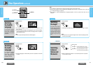
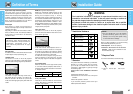
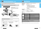
Power connector
Remote control
signal receiver
Double-sided tape
Attaching the remote
control signal receiver
R (Red)
Video
(Yellow)
Video
(Yellow)
L (White)
(Black)
(Black)
R (Red)
L (White)
By performing this connection, remote control
signals can be received by the monitor unit.
(Do not connect the remote control signal receiver
when this connection has been performed.)
When connecting or disconnecting the cord, be
absolutely sure to take hold of the molded part of the
plug (and not the cord itself) and proceed.
Power connector
Power socket
Remote control
signal receiver lead
VTR1
input lead
CY-VMX6800U (option)
6
Cord clamp
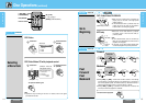
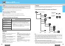
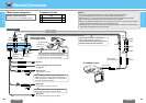
Caution:
≥ This product is designed to operate with a 12 V DC, negative ground battery system.
≥ To prevent damage to the unit, be sure to follow the connection diagram below.
≥ Remove approx.
1
/4z (5 mm) of protective covering from the ends of the leads before connecting.
≥ Do not insert the power connector into the unit until the wiring is completed.
≥ Be sure to insulate any exposed wires from a possible short-circuit from the car chassis. Bundle all
cables and keep cable terminals free from touching any metal parts.
≥ Remember, if your car has a drive computer or a navigation computer, the data of its memory may be
erased when the battery terminals are disconnected.
1
1
Q’ty
Power Connector
Cord Clamp
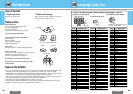
❐ Basic System Configuration ❐ Accessories for Use
Examples of system combination:
≥ Color LCD monitor (CY-VMX6800U, option)