


3
Connections
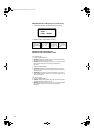
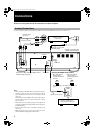
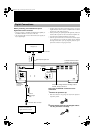
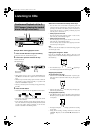
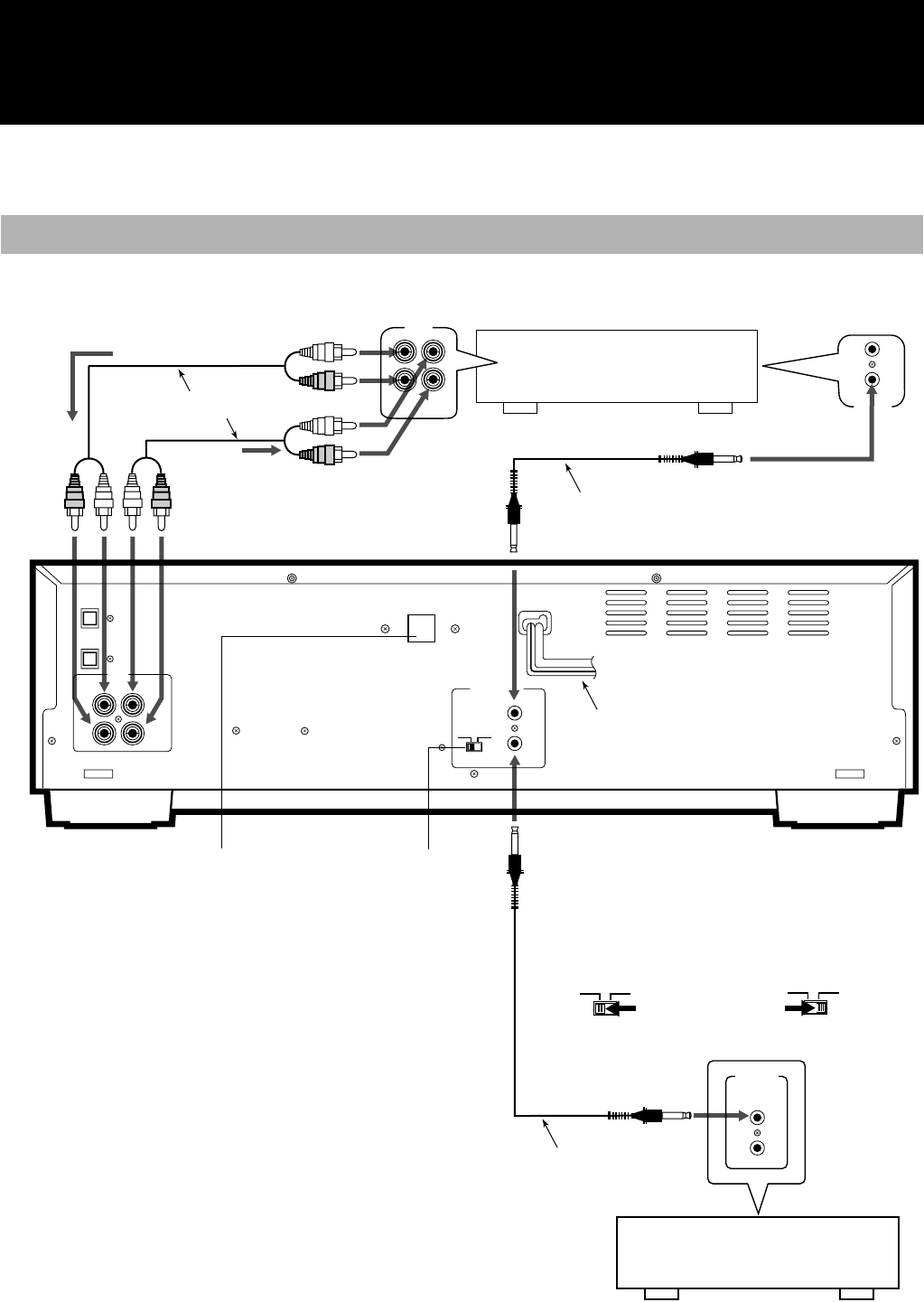
Do not turn on the power until all the connections have been completed.
Use the accessory pin cables to connect this unit’s LINE connectors with the TAPE/CDR connectors on the receiver, etc.
Analog Connections
DIGITAL IN
OPTICAL
DIGITAL OUT
OPTICAL
LINE
COMPU LINK
-
4
(SYNCHRO)
MODE
CDR TD
IN REC
( )
OUT PLAY
LEFTLEFT
RIGHTRIGHT
TAPE
/CDR
IN
(PLAY)
OUT
(REC)
COMPU LINK
-
4
SYNCHRO
COMPU LINK
-
3
SYNCHRO
( )
VOLTAGE SELECTOR
CDR
MODE
TD
Recording signals
(line input)
Accessory pin cables
Playback signals
Amplifier, receiver etc.
made by JVC
Accessory connecting cable
(with black plugs)
XL-R5000 CD/CDR MULTIPLE
COMPACT DISC RECORDER
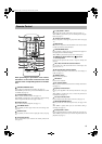
MODE switch
Selecting the MODE switch position
• When connected with
CDR input/output
terminals of the amplifier
or receiver
• When connected with
TAPE input/output
terminals of the amplifier
or receiver
• For further details on the COMPU LINK function, see
page 37.
Optional connecting cable
CD player, cassette deck or
other component made by JVC
Note
• Before selecting the COMPU LINK-4 mode (CDR or TD), dis-
connect the power cord from the power outlet to turn off the
power. The function will not be set if it is selected while the
power is on.
Alternatively, when the COMPU LINK-4 mode (CDR or TD) is
selected while the power is on, disconnect the power cord and
then re-connect it.
• Misconnections can be avoided by using the white plugs on the
accessory pin cables for the LEFT channel and the red plugs for
the RIGHT channel.
• Insert the plugs all the way in. Incomplete connections may
cause noise.
• When plugging the power cord into the AC outlet, be sure to
match the width of the plug blades with the outlet.
CDR
MODE
TD
Power cord
Units have a voltage selector excluding units for
Canada, Europe, and U.S.A.
XL-R5000.book Page 3 Wednesday, March 29, 2000 6:37 PM