


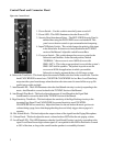
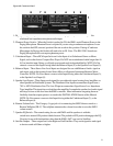
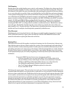
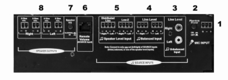
1 - Paging Microphone Input – This is the Connection for a Paging Microphone. It is designed for
a balanced low impedance microphone audio input.
2 - Phantom Power Switch – When the Switch is pushed in ON, the SMS1 sends Phantom Power to the
Paging Microphone. Phantom Power is required if you are using a condenser microphone. Leave
the switch in the OFF, outward, position if the mic works in this position. If using a Condenser
Microphone for Paging, this Switch will need to be set IN. Note: The JBL Z-M1 Soundzone
Paging Microphone does not require phantom power.
3 - Unbalanced Input – These RCA Input Jacks are for the Input of an Unbalanced Stereo or Mono
Signal, such as that from a Compact Disc Player. Do NOT run an unbalanced cable longer than 16
ft (5 m) into this input. Doing so will pick up noise and result in degraded fidelity. NOTE: Do Not
connect a source to this Input if using either the Balanced Input (4) or the Speaker Level Input (5).
4 - Balanced Input – These Stereo Line Level Inputs are designed for use with Balanced Audio signal on
each input, such as that coming from a Stereo Mixer or a Separate Soundzone Business Music
Controller. NOTE: Do Not connect a source to this Input if using either the Unbalanced Input (3),
or the Speaker Level Input (5).
5 - Speaker Level Inputs – These Inputs are designed for use with audio signal coming from Amplifiers or
other Speakers in Distributed Systems. The Distributed Line Input accommodates Signal from a
70V or 100V Distribution Line. The Low-Z Input accommodates Signal from a Low-Impedance
Type Amplifier. This input does not loaddown the amplifier. It samples the speaker level audio signal
and drops it down to line level into the SMS1 controller. More information on getting the most
flexibility from these input options is covered in the INSTALLATION Section of this Manual.
NOTE: Do Not connect a source to this Input if using either the Unbalanced Input (3), or the
Balanced Input (4).
6 - Remote Volume Jack – This Category-5 type jack is for connecting the SMS Volume control to a
Remote Wallplate (ZR-V). The wallplate attenuates the volume from what is set on the SMS1
volume control.
7 - Speaker EQ Switch – The normal setting for use with SMS1 satellite speakers is with this
switch in its outward ON position labeled normal. The pushed-in OFF position disengages the EQ
Circuitry for use with loudspeakers other than the SMS1-SAT’s are used as Satellites.
8 - Satellite Outputs – These outputs are for the Right and Left Satellites. They are designed to send signal
to devices rated at 8 Ohms or higher.
Figure 4b: Connector Panel
6