


Control Panel and Connector Panel
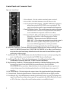
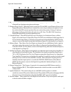
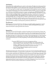
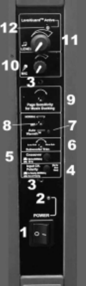
Figure 4a: Control Panel
1 - Power Switch – Use this switch to turn the System on and off.
2 - Power LED – This LED illuminates when the Power is ON.
3 - Security Panel Attachment Points – The INCLUDED Security Panel is
attached here using the INCLUDED screws and standoffs. This
panel covers the trim controls to prevent unauthorized tampering .
4 - Input CH Polarity Switch – This switch changes the polarity of the input
to the Subwoofer. Its function is clearly detailed in the TUNING
section of the Manual. Adjust this switch for most Bass.
5 - Crossover Switch – This switch changes the crossover point for the
Subwoofer and Satellites. In the outward position, labeled
“NORMAL,” the crossover is set at 160 Hz (for use with
SMS1-SAT’s). This is the proper position for use with the system’s
SMS1-SAT satellite speakers. The pushed-in position sets the
crossover at 80 Hz for applications in which you need the
Subwoofer to simply augment the bass of a full-range system.
6 - Subwoofer Trim Knob – This knob adjusts the amount of Subwoofer level in the acoustic mix. Turn the
knob CLOCKWISE for more bass, COUNTER-CLOCKWISE for less Bass. LevelGuard may
not protect the sytem from damage when the subwoofer trim control is turned all the way up. Be
careful not to set this too high.
7 - AutoWarmth LED – This LED illuminates when the AutoWarmth circuitry is actively responding to the
music. AutoWarmth is covered in detail in the TUNING Section of the Manual.
8 - AutoWarmth Trim Knob – This knob adjusts the amount of AutoWarmth in the Signal Path.
AutoWarmth is covered in detail in the TUNING Section of the Manual.
9 - Page Sensitivity Trim Knob – This knob adjusts the sensitivity of the Page Ducking circuitry to the
incoming Page Signal. Turn CLOCKWISE for greater Sensitivity, turn
COUNTER-
CLOCKWISE
for less sensitivity. Adjust this control so the mic makes the music go down in
volume during a page, but so that the page ducking does not falsely trigger when a page isn’t
occuring.
10 - Mic Volume Knob – This knob adjusts the output volume of the signal from the Paging Microphone.
11 - Volume Knob – This knob adjusts the music volume but does NOT affect the mic paging volume.
12 - LevelGuard LED – This LED illuminates when the LevelGuard Circuitry is actively responding to the
signal. LevelGuard lowers high volume signals. It’s acceptable for this LED to flash on for as much
as 50% of the time, as long as the sound from the speakers is not audibly distorted.
5