


8 En
Functional Overview
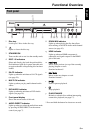
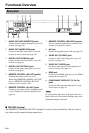
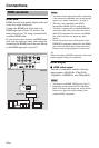
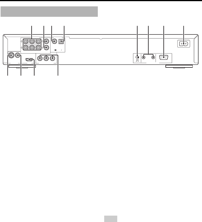
1 AUDIO OUT (6CH DISCRETE) jacks
Connect to the 6-channel input jacks of your AV
receiver (see page 10).
2 AUDIO OUT (MIXED 2CH) jacks
Connect to the audio input jacks of your AV
receiver or stereo system (see page 10).
3 DIGITAL OUT (COAXIAL) jack
Connect to the coaxial input jack of your AV
receiver (see page 9).
4 DIGITAL OUT (OPTICAL) jack
Connect to the optical input jack of your AV
receiver (see page 9).
5 REMOTE CONTROL (ON, OFF) switch
Switches the remote control on or off.
When using REMOTE CONTROL (IN, OUT)
jacks or REMOTE CONTROL (RS-232C)
terminal, set this switch to ON.
6 REMOTE CONTROL (IN, OUT) jacks
Connect to the remote control output/input jack
of your Yamaha AV receiver/component (see
page 14).
7 REMOTE CONTROL (RS-232C) terminal
Use as an expansion terminal for commercial use.
Consult your dealer for details.
8 AC inlet
Connect the supplied power cable (see page 14).
9 VIDEO OUT (S VIDEO) jack
Connect to the S-video input jack of your AV
receiver (see page 11).
0 VIDEO OUT (VIDEO) jack
Connect to the composite video input jack of
your AV receiver (see page 11).
q HDMI jack
Connect to the HDMI input jack of your HDMI
component (see page 12).
w COMPONENT VIDEO OUT (Y, PB, PR)
jacks
Connect to the component input jacks of your
AV receiver (see page 11).
Do not touch the inner pins of the jacks on the rear
panel of this unit. Electrostatic discharge may cause
permanent damage to this unit.
■ RS-232C terminal
The REMOTE CONTROL (RS-232C) terminal is used in custom installation. Do not connect
any cables to this terminal during normal use.
Rear panel
S VIDEO VIDEO
VIDEO OUT HDMI
MIXED 2CH
OPTICALCOAXIAL
PCM DIGITALDTS
AUDIO OUT DIGITAL OUT
FRONT SUB WOOFER SURROUND
6CH DISCRETE
P
R PB Y
COMPONENT VIDEO OUT
REMOTE CONTROL
OUTONOFF IN
RS-232C
CENTER
L
R
L
R
1234 56 7 8
90 wq
Note