13
MZ-DH10P
2. OPERATION IN SETTING THE TEST MODE
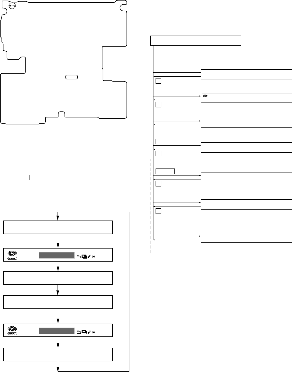
• When the test mode becomes active, first the Display Check
mode is selected.
• Other mode can be selected from the Display Check mode.
• When the test mode is set, the LCD repeats the following
display.
• When the x key is pressed and hold down, the display at that
time is held so that display can be checked.
Display check mode:
OUTLINE
Operation in the test mode is performed with the set. A key having
no particular description in the text, indicates a set key. Also, For
the LCD display, the LCD on the remote commander is shown.
1. ENTERING THE TEST MODE
Short SL801 on the MAIN board with a solder bridge. Then, turn
on the power.
SECTION 4
TEST MODE
Display Check Mode
Version display
→
All lit
→
All off
→
Version display...
[VOL +]
key
x
key
x
key
u
ENT
key
x
key
>
key
x
key
[DOWNLOAD]
key
[DISPLAY]
key
[VOL --]
key
x
key
Open the lid
Manual Mode
Sound Skip Check Result
Display Mode (Play)
Self-Diagnosis Result Display Mode
Sound Skip Check Result
Display Mode (REC)
Key Check Mode
Overall Adjustment Mode
Key Count Mode
[DISPLAY]
key
(press a
few seconds)
[DISPLAY]
key
(press a few seconds)
(Not used in servicing)
000 Manual
000 1 0000
000 P00r00
000 p00R00
000 MENU 000
110 10
000 AdjF**
012 V1.000
– MAIN BOARD (Conductor Side) –
SL801
All lit
Remote commander LCD display
All off
All lit
All off
Back-end FW
version display
Front-end FW
version display
888
012 V*.***
F
1SHUFPGM SOUND
V-SUR
8
888
012 ******
F
1SHUFPGM SOUND
V-SUR
8
3. RELEASING THE TEST MODE
Turn off the power and open the solder bridge on SL801 on the
MAIN board.
Note1: Remove the solders completely. Remaining could be shorted with
the chassis, etc.
Note2: When the power supply is switched on in the state where all
electrical adjustments have not finished, it is displayed on LCD as
“Error EE’’ and the usual operation can’t be performed. When a
power supply is accidentally turn off in the middle of electrical
adjustments, it is again set as test mode and electrical adjustments
is mode to complete.
4. CONFIGURATION OF THE TEST MODE
Flow of the test mode:


