


16
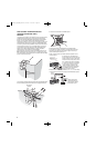
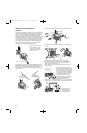
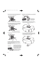
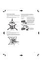
9. Place the large end of the multiunit wiring adapter that is already installed in
speaker 2 into speaker 3 by sliding a multiunit wiring adapter into the
rear of it at a slight angle and rotate clockwise.
10. Connect the terminal assembly to the back of the second multiunit wiring
adapter. It will snap securely into place. The other end of the multiunit
wiring adapter will already be connected to the other speaker already
mounted in the corner/wall-mount bracket assembly.
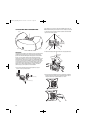
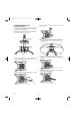
11. Connect the wires to the terminal assembly and place the speaker on
the remaining bracket.
IMPORTANT: Make sure all equipment is turned off before making
any connections. For speaker connections, use a high-quality speaker wire
with polarity coding. The side of the wire with a ridge or other coding is
usually considered positive polarity (i.e., +).
NOTE: If desired, consult your local JBL dealer about speaker wire and
connection options.
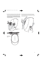
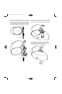
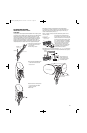
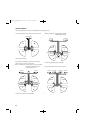
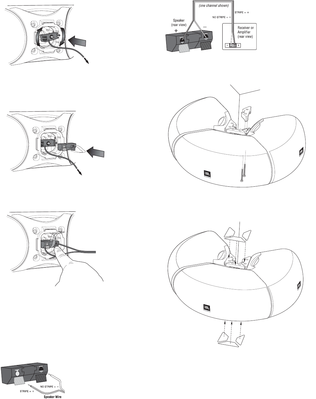
The speakers have coded terminals that
accept a variety of wire connectors. The most
common connection is shown in the diagram
to the left. To ensure proper polarity, connect
each + terminal on the back of the amplifier
or receiver to the respective + (red) terminal
on each speaker, as shown. Connect the
– (black) terminals in a similar way. See
the owner’s guides that were included with
your amplifier, receiver and television to
confirm connection procedures.
IMPORTANT: Do not reverse polarities (i.e., + to – or – to +) when making
connections. Doing so will cause poor imaging and diminished bass response.
Wiring diagram shows
polarity connections for
one channel of a stereo or
home theater system.
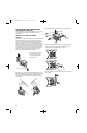
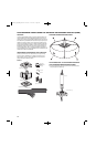
12. Rest the third JBL Control NOW speaker’s rear flange in the mounting
bracket as shown and complete the process. Secure the mounting-bracket
cap with 2 screws through the bottom of the mounting bracket.
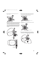
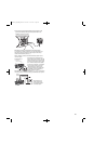
13. To orient the JBL logo into the correct position, pull the JBL logo slightly
outward from the speaker grille and rotate. The JBL logo is held in place
by a spring. Peel the adhesive cover off the mounting-bracket covers and
attach to top and bottom of mounting-bracket assembly.
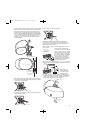
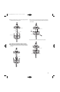
Speaker 1
Speaker 2
Speaker 3
Mounting-Bracket
Covers
Mounting-Bracket
Covers
RED = +
BLACK = —
Standard
Connection
RED = +
BLACK = —
1. Strip 1/4" of wire
2. Press and push connector
3. Insert bare end;
release push connector
This end is connected to the second speaker currently
resting in the Corner/Wall-Mount-Bracket Assembly.
This end is connected to the second speaker currently
resting in the Corner/Wall-Mount Bracket assembly.
JBLP2605_CN_CNAW_PM-OM 4/23/08 12:57 PM Page 16