


EVOi.net
6
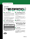
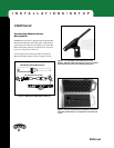
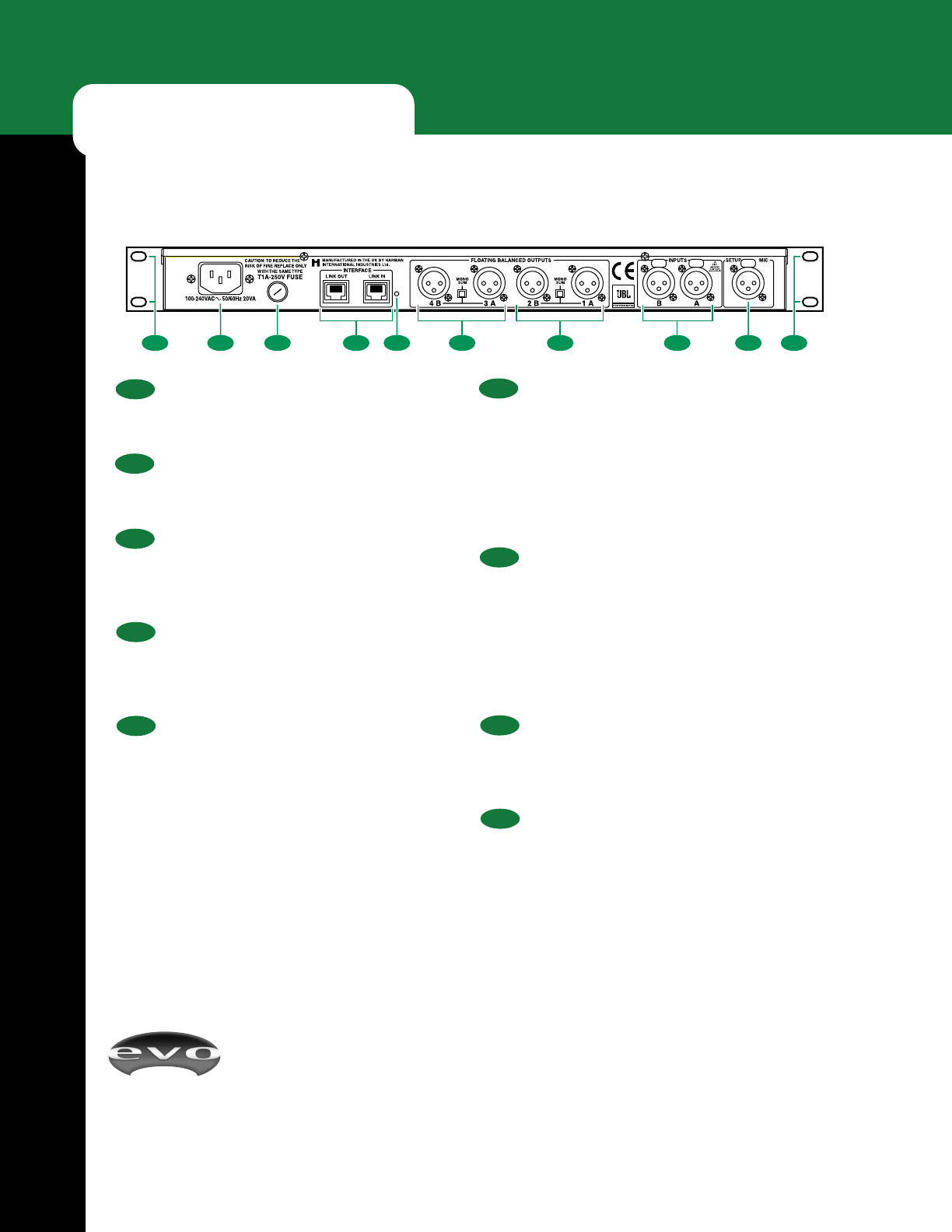
10 RU Mounting Holes
The EVOi.net is equipped with four mounting holes for
installation in one RU (rack unit) space.
11 Power Connector
Insert the enclosed power cord into the IEC connector to
supply the specified AC power.
12 Fuse
The removable fuse protects internal circuits. When
replacing the fuse, be sure to use the same type as speci-
fied.
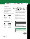
13 INTERFACE Connectors
Two 8-pin RJ-45/Shellnet connectors, labeled LINK IN and
LINK OUT, will provide interlinking to other EVOi.net
units. Functionality will be determined at a later date.
14 Lockout Switch
To protect settings from being inadvertently changed, press
this recessed button once to disable TEST, AUTO EQ
SETTING, AEQ ON, and DELAY SET and to lock their
parameters. The orange LOCKED LED (under SET-
TINGS on the front panel) will turn on to confirm the
lockout. To restore functionality and to change settings,
press this recessed button once again.
FEATURES
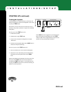
REAR PANEL
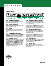
15 OUTPUTS (4B/3A), Auxiliary
Two 3-pin male XLR connectors for right (4B) and left
(3A) connection to auxiliary EVOi.324 loudspeakers using
a pair of XLR signal cables.
For mono operation, press MONO SUM to sum the input
signals and route the combination to both outputs. The
mono signal level will be 4 dB lower than the stereo level.
16 OUTPUTS (2B/1A), Main
Two 3-pin male XLR connectors for right (2B) and left
(1A) connection to main EVOi.324 loudspeakers using a
pair of XLR signal cables.
For mono operation, press MONO SUM to sum the input
signals and route the combination to both outputs. The
mono signal level will be 4 dB lower than the stereo level.
17 INPUTS (B/A)
Two 3-pin female XLR connectors for right (B) and left (A)
connection to the EVOi.sys R MIX OUTPUTS L using a
pair of XLR signal cables.
18 SETUP MIC
A 3-pin female XLR connector for connection to the
enclosed measurement microphone using the supplied 100’
XLR signal cable.
Figure 3
1110 1014 1812 13 15 16 17