


HP P2000 G3 SAS MSA System User Guide 35
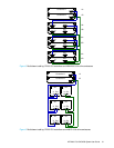
DC model
Locate the two DC power cables provided with your controller enclosure.
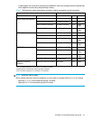
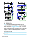
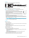
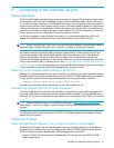
Figure 13 DC Power cable featuring sectioned D-shell and lug connectors
See Figure 13 and the illustration at left (in Figure 12) when performing the following steps:
1. Verify that the enclosure’s power switches are in the Off position.
2. Connect a DC power cable to each DC power supply using the D-shell connector.
Use the UP> arrow on the connector shell to ensure proper positioning (see adjacent
left side view of D-shell connector).
3. Tighten the screws at the top and bottom of the shell, applying a torque between 1.7
N-m (15 in-lb) and 2.3 N-m (20 in-lb), to securely attach the cable to the DC power
supply module.
4. To complete the DC connection, secure the other end of each cable wire component
of the DC power cable to the target DC power source.
Check the three individual DC cable wire labels before connecting each cable wire lug to its power
source. One cable wire is labeled ground (GND) and the other two wires are labeled positive (+L) and
negative (-L), respectively (shown in Figure 13 above).
CAUTION: Connecting to a DC power source outside the designated -48V DC nominal range
(-36V DC to -72V DC) may damage the enclosure.
Power cycle
To power on the system:
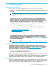
1. Power up drive enclosure(s).
Press the power switches at the back of each drive enclosure to the On position. Allow several seconds
for the disks to spin up.
2. Power up the controller enclosure next.
Press the power switches at the back of the controller enclosure to the On position. Allow several
seconds for the disks to spin up.
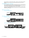
To power off the system:
1. Stop all I/O from hosts to the system.
2. Shut down both controllers using either method described below:
• Use SMU to shut down both controllers, as described in the online help and HP P2000 G3 MSA
System SMU Reference Guide.
Proceed to step 3.
• Use the command-line interface (CLI) to shut down both controllers, as described in the HP
P2000G3MSA System CLI Reference Guide.
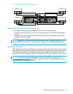
3. Press the power switches at the back of the controller enclosure to the Off position.
4. Press the power switches at the back of each drive enclosure to the Off position.
+L
GND
-L
+L
GND
-L
+L
GND
-L
+L
GND
-L
Connector pins (typical 2 places)
Connector (front view)
Ring/lug connector (typical 3 places)
D-shell
(left side view)