


32 Installing the enclosures
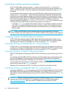
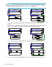
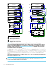
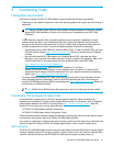
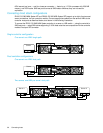
Figure 10 Cabling connections between dual controllers and drive enclosures of mixed type
The figure above shows a sample fault-tolerant cabling scenario on left, and a straight-through cabling
scenario on right. Both diagrams show drive enclosures of mixed type. Do not mix SAS1.1 and SAS2.0
expanders, except as described in Additional cabling considerations on page 26. Avoid mixing them
except when upgrading legacy systems.
In the illustration on the left, note that the D2700 6Gb drive enclosures could alternatively be cabled before
the P2000 6Gb drive enclosures. The illustration at the right shows a D2700 6Gb drive enclosure before a
P2000 6Gb drive enclosure, MSA70 3Gb drive enclosure, and MSA2000 3Gb drive enclosure. Note that
the MSA2000 3Gb drive enclosure is cabled after the other drive enclosures, using straight-through
cabling.
Although 6Gb drive enclosures can be cabled after an MSA70 3Gb drive enclosure, performance of the
6Gb devices will be limited to 3Gb.
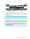
IMPORTANT: For comprehensive configuration options and associated illustrations, refer to the HP
P2000G3MSA System Cable Configuration Guide.
1B
1A
Controller B
Controller A
Out
In
Out
In
3B
3A
P1
P1
4B
4A
P2
P2
P2
P2
P1
P1
5B
5A
2B
2A
Out
In
Out
In
Controller B
Controller A1A
1B
5B
5A
Fault-tolerant cabling
Straight-through cabling
In
In
Out
Out
4A 4B
P1
P1
P2
P2
3B
3A
OutIn
In
In
Out
Out
2B
2A
OutIn
2
1
3
4
1
1
2
2
= P2000 6Gb drive enclosure
1
= D2700 6Gb drive enclosure
2
= MSA70 3Gb drive enclosure
3
= MSA2000 3Gb drive enclosure
4
Drive enclosure IOM face plate key: