


30 Installing the enclosures
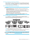
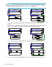
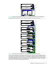
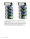
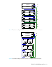
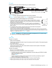
Figure 7 Cabling connections between P2000 G3 controllers and D2700 6Gb drive enclosures
The figure above provides sample diagrams reflecting cabling of P2000 G3 controller enclosures and
D2700 6Gb drive enclosures.
The diagram at left shows a dual-controller enclosure cabled to D2700 6Gb drive enclosures featuring
dual-expansion modules. Controller module 1A is connected to expansion module 2A, with a chain of
connections cascading down (blue). Controller module 1B is connected to the lower expansion module
(5B), of the last drive enclosure, with connections moving in the opposite direction (green).
The diagram at right shows the same storage components connected using straight-through cabling.
P1
Controller A
Controller B
1A
1B
P2P1
P1
P1
P1
P1
P2P1
P2P1
2A
2B
3A
3B
4A
4B
5A
5B
P2
P2
P2
P2
P2
P1
Controller A
Controller B
P2
P1
P2
P1
P2
P1
P2
P1 P2
P1 P2
1A
1B
2A
2B
3A
3B
4A
4B
5A
5B
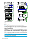
Fault-tolerant cabling Straight-through cabling
P1
P2
P1
P2