


28 Installing the enclosures
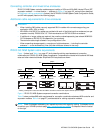
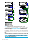
NOTE: For clarity, the schematic illustrations of controller and expansion modules shown in this section
provide only relevant details such as expansion ports within the module face plate outline. For detailed
illustrations showing all components, see Rear panel components on page 19.
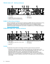
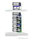
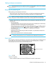
Figure 2 Cabling connections between P2000 G3 MSA System controllers and P2000 6Gb drive
enclosures
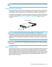
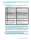
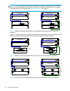
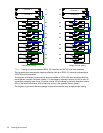
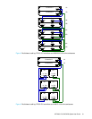
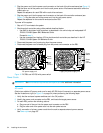
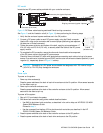
Figures 2 - 4 show a single controller module connected to a single expansion module (illustrations on left),
with dual controller modules connected to dual expansion modules (illustrations on right).
Figure 3 Cabling connections between P2000 G3 controllers and D2700 6Gb drive enclosures
Figure 4 Cabling connections between P2000 G3 controllers and MSA2000 3Gb drive enclosures
In Out
1A
2A
Controller A
In Out
1B
1A
2A
2B
Controller A
Controller B
In Out
P1 P2
1A
2A
Controller A
P1 P2
1A
2A
Controller A
Controller B
P1 P2
1B
2B
In Out
1B
1A
2A
2B
Controller A
Controller B
In Out
In Out
1A
2A
Controller A