


DIGITAL RADIO GUIDE TERRESTRIAL TRANSMISSION SYSTEMS - DRM
17
QAM is used for the modulation that is impressed upon the subcarriers to convey
the information. Two primary QAM constellations are used: 64-QAM and 16-QAM.
The former provides the highest audio quality, but is less robust than the latter. In
addition, a 4-QAM (QPSK) signal, which is very robust, is used for some of the
signalling (but not for the MSC).
The interleaver time span (applied to the MSC) for HF transmission is around 2.4
seconds to cope with time and frequency selective fading by protecting the audio
and data from rapid fades during the natural sequence of speech and music.
Owing to the less difficult propagation conditions for the LF and MF bands, a
shorter interleaver of around 0.8 seconds can be used.
The multi-level convolutional coding scheme uses code rates in the range between
0.5 and 0.8, with the lower rate being associated with the difficult HF propagation
conditions. A 0.5 code rate means that only half the transmitted bits within the
overall coded block are used for the actual services in the multiplex, whereas a 0.8
rate means 80% are.
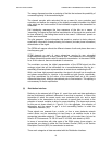
4.1.3 Transmitter Considerations
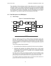
Beyond the modulator box in Figure 4.1 is the transmitter exciter. The DRM system
exciter can be used to impress signals on either linear or non-linear transmitters. It is
expected that high-powered non-linear transmitters will be the more usual way of
transmitting, much as is done now with analogue modulation. However, there are
broadcasting service situations where very low powered linear transmissions could be the
best way to serve the public.
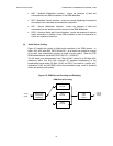
With respect to non-linear amplification (Class C operation), the incoming DRM signal
needs to be split into its amplitude and phase components prior to final amplification.
Using QAM modulation, there is a small discrete set of possible amplitudes and phases.
The amplitude component is passed via the anode circuitry; the phase component is
passed through the grid circuitry. These are then combined with the appropriate time
synchronization to form the output of the transmitter.
Measurements of the output spectra show the following: the energy of the digital signal is
more or less evenly spread across the 9 or 10 kHz channel, the shoulders are steep at
the channel edges, and drop rapidly to 40 dB or so below the spectral density level within
the assigned channel, and the power spectral density levels continue to decrease beyond
the 4.5 or 5 kHz from the central frequency of the assigned channel with a rapidity that
permits conformance to the ITU-R mask for the use of the channels.
(1) Over the air
The digital phase/amplitude information on the RF signal is corrupted to different
degrees as the RF signal propagates. Some of the HF channels provide
challenging situations of fairly rapid flat fading, multipath interference that produces
frequency-selective fading within a channel and large path delay spreads of a few
milliseconds or more, and ionospherically induced high levels of Doppler spreads
on the order of 1 or more hertz.
The error protection and error correction incorporated in the DRM system design
mitigates these effects to a great degree. This permits the receiver to accurately
decode the transmitted signal information.