


DIGITAL RADIO GUIDE TERRESTRIAL TRANSMISSION SYSTEMS - DRM
16
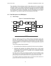
FAC provides information on the signal bandwidth and other such parameters, and
is also used to allow service selection information for fast scanning. The SDC gives
information to a receiver on how to decode the MSC, how to find alternative
sources of the same data, and gives attributes to the services within the multiplex.
The MSC multiplex may contain up to 4 services, any one of which can be audio or
data. The gross bit rate of the MSC is dependent on the channel bandwidth and
transmission mode being used. In all cases, it is divided into 400 millisecond
frames.
The FAC’s structure is also built within a 400 millisecond frame, and is designed
without interleaving, for example, to ensure rapid delivery of the information it
contains. The design without interleaving is also to ensure fastest decoding of
basic data by the Rx before it can do the audio decoding. The channel parameters
are included in every FAC frame segment. The service parameters are carried in
successive frames, one service per frame. The names of the FAC channel
parameters are: base/enhancement flag, identity, spectrum occupancy, interleaver
depth flag, modulation mode, number of services, reconfiguration index, and
reserved for future use. These use a total of 20 bits. The service parameters within
the FAC are: service identifier, short identifier, conditional access, language,
audio/data flag, and reserved for future use. These use a total of 44 bits.
The SDC’s frame periodicity is 1200 milliseconds. The fields of information are:
multiplex description, label, conditional access, frequency information, frequency
schedule information, application information, announcement support and
switching, coverage region identification, time and date information, audio
information, FAC copy information, and linkage data. As well as conveying these
data, the fact that the SDC is inserted periodically into the waveform is exploited to
enable seamless switching between alternative frequencies.
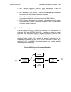
(5) Channel coding and modulation
The coding/modulation scheme used is a variety of coded orthogonal frequency
division multiplexing (COFDM), which combines the OFDM with the Multi-Level
Coding (MLC) based upon convolutional coding. The convolutional coding provides
a level of error protection. These two main components are supplemented by time
interleaving (“scrambling” of the bit stream) and the provision of pilot
(predetermined value) cells for instantaneous channel estimation. All of this
mitigates the effects of short-term signal fading, whether selective or flat.
Taken together, this combination provides excellent transmission and signal
protection possibilities in the narrow 9 or 10 kHz channels in the LF, MF and HF
broadcasting frequency bands. It can also be used for “multi-channel” DRM use;
that is 18 or 20 kHz channels, using 2 contiguous ITU-R channels. This level of
bandwidth will permit good stereo broadcasting.
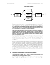
For OFDM, the transmitted signal is composed of a succession of symbols, each
including a “guard interval,” which is a cyclic time prefix that provides a “dead time”
to counter intersymbol interference due to multipath delay spread. Orthogonality
refers to the fact that, in the case of the design of the DRM system, each symbol
contains around between 100 and 200 subcarriers spaced evenly across the 9 or
10 kHz channel in such a way that their signals do not interfere with each other
(are orthogonal). The precise number of subcarriers, and other parameter
considerations, are a function of the actual letter modes used: ground wave, sky
wave, and highly robust transmissions.