


DIGITAL RADIO GUIDE TERRESTRIAL TRANSMISSION SYSTEMS - DRM
13
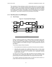
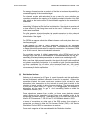
The energy dispersal provides an ordering of the bits that reduces the possibility of
unwanted regularity in the transmitted signal.
The channel encoder adds redundant bits as a means for error protection and
correction and defines the mapping of the digitally encoded information into QAM
cells, which are the basic carriers of the information supplied to the transmitter for
modulation.
Cell interleaving rearranges the time sequence of the bits as a means of
“scrambling” the signal so that the final reconstruction of the signal at a receiver will
be less affected by fast fading than would be the case if “continuous” speech or
music were transmitted.
The pilot generator injects information that permits a receiver to derive channel-
equalization information, thereby allowing for coherent (includes phase information)
demodulation of the signal.
The OFDM cell mapper collects the different classes of cells and places them on a
time-frequency grid.
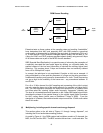
OFDM depends on each of many subcarriers carrying its own sinusoidal
amplitude/phase signal for a short period of time. The ensemble of the information
on these subcarriers contains what is needed for transmission. In the case of DRM,
for a 10 kHz channel, there are hundreds of subcarriers.
The modulator converts the digital representation of the OFDM signal into the
analogue signal that will be transmitted via a transmitter/antenna over the air –
essentially phase/amplitude representations as noted above modulating the RF.
With a non-linear high-powered transmitter, the signal is first split into its amplitude
and phase components for injection in the anode and grid circuits, respectively,
and then recombined (by the action of the transmitter itself set at the correct
differential delay time), and then recombined prior to final emission. This splitting is
not necessary for linear amplification.
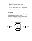
(2) Distribution Interface
Referring to the extreme left of Figure 4.1, apart from audio and data applications
that are multiplexed, additional information is sent that is required to instruct the
transmitter to select the correct mode, error protection level, etc. and to send
information in the transmission to the receivers to permit them to switch to the
selection of several variables to allow for proper decoding. (The boxes and arrows
for this are not shown directly in Figure 4.1.) In the aggregate, this collection of
information and the means to get it to the transmitting station is called the
“Distribution Interface” (DI).
These signals can emanate from a studio, or from a more elaborate network
control centre, and be transmitted via land lines or via satellite circuits to the
appropriate transmitter station(s). These details will not be noted here, but can be
found in ETSI documents TS 102 821 and TS 102 820, both dated July 2003.
In terms of connections with other parts of the DRM system, these signals, as
appropriate, are placed in either the Fast Access Channel (FAC) or the Service
Description Channel (SDC) for transmission to receivers.
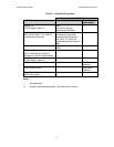
There are 4 categories of data associated with the Distribution Interface: