


LBI-39175
A
7
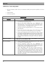
ALIGNMENT PROCEDURES
INTRODUCTION
All operations of this radio are controlled by an
embedded digital computer, which is programmed with a
personality unique to the customer. In order to align and
test the radio, it must be programmed with a specific test
personality, which will allow conventional operation on
certain test frequencies. Furthermore, certain commands,
known as Test Mode Commands, cause the radio to
perform specific test functions. These will be noted as
required in the following alignment and troubleshooting
instructions.
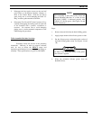
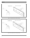
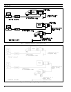
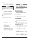
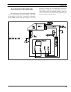
In order to program an ORION personality, the
radio and control unit must first be connected to a
Personal Computer via a PC Programming Cable and
hardware Programming Interface TQ3370 in one of the
configurations shown in Figures 2 and 3. Accessories
may be connected to the appropriate Accessory Cable
19B802554P1-P4 as needed.
The PC must be equipped with the PC
Programming Software Version 4.0 or later. It is assumed
in this manual that the Service Technician is familiar with
the operation of the PC Programming Software Programs.
Consult the PC Programming Software manuals for
further details regarding this software.
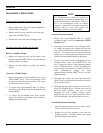
Before bench testing the radio, be sure of the output
voltage characteristics of your bench power supply.
To protect the transmitter power output transistors
from possible instant destruction, the following input
voltages must not be exceeded
Transmitter unkeyed: 16.5 Volts
Transmitter keyed 16.3 Volts
(50 ohms resistive load)
Transmitter keyed 14.0 Volts
(no load or non-resistive load):
These voltages are specified at the normal vehicle
battery terminals of the radio and take the voltage
drop of standard cables into account. The voltage
limits shown for a non-optimum load is for "worst
case" conditions. For antenna mismatches likely to
be encountered in practice, the actual limit will
approach the 16.3 Volt figure.
Routine transmitter tests should be performed at EIA
Standard Test Voltages (13.6 VDC for loads of 6 to
16 amperes; 13.4 VDC for loads of 16 to 36
amperes). Input voltages must not exceed the limits
shown, even for transient peaks of short duration.
Many commonly used bench power supplies cannot
meet these requirements for load regulation and
transient voltage suppression. Bench supplies which
employ "brute force" regulation and filtering (such as
Lapp Model 73) may be usable when operated in
parallel with a 12 Volt automotive storage battery.
CAUTION