


L
BI-39175A
4
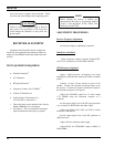
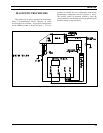
DISASSEMBLY PROCEDURE
To Remove the Unit from the Mounting Bracket
1. Remove Microphone, Power, and Accessory/Remote
Control Cables, as required.
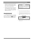
2. Remove the lock screws at the side of the radio unit,
using a No. 20 TORX
driver.
3. Pull the radio, and remove the mounting bracket.
To Gain Access to the Circuitry for Servicing
RF Power Amplifier Module
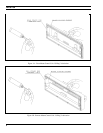
1. Remove the waterproof cover on the bottom of the
module, using #20 TORX
driver. Note that the four
mounting screws are captive.
2. Remove the inner shield by pulling the attached
handle.
Transceiver (TXRX) Module
1. Remove the waterproof top and bottom covers, using
a #20 TORX
driver. Four cover mounting screws
are located on the bottom of the module. The screws
on the bottom cover are captive.
2. To expose the Logic/Audio/455 kHz IF circuitry,
remove the shield on top of the module by pulling the
attached handle.
3. To expose the Exciter/RX Front End circuitry,
remove the shield on the bottom of the module by
pulling the attached handle.
The VCO/Synthesizer circuitry is exposed by
removing the screws from the shield casting, also
located on the bottom of the module. However,
this is not recommended, except on extreme
situations. If the shield is removed, it should be
replaced using the exact screw torque and
installation sequence given in LBI-38909.
NOTE
Control Unit (Front Mounted)
1. Expose the Logic/Audio/455 kHz IF circuitry
according to Steps 1 and 2 in
Transceiver (TXRX)
Module
section.
2. Disconnect Flex Circuit PC2 from Connector J701,
by carefully disengaging the locking tab from each
side of the connector with a jeweler's screwdriver or
tweezers. Use extreme care to avoid damaging the
plating runs or surface-mounted components on the
printed wire board (PWB) during this procedure.
3. Turn the radio upside down, and disengage the two
mounting screws, using a #10 TORX
driver. Be
sure to engage the screws in the captivation threads
on the Transceiver chassis. Do this by pulling each
screw upwards with tweezers or needle nose pliers,
while simultaneously turning the screw
counterclockwise with the TORX
driver. See LBI-
38909 for details.
4. Disengage the control unit from the Transceiver
chassis using a pivoting motion about the top edge of
the Transceiver chassis.
5. Disengage the four captive screws on the rear cover,
using a #10 TORX
driver. Slide the rear cover off
the Front Panel Assembly, using care to avoid
damaging the black "O-Ring" moisture gasket
attached to the rear cover. Note that the Flex Circuit
PC2 slides through a slot opening on the rear cover.
Control Head (Remote Mounting)
1. Disconnect Remote Control and Accessory cables,
using a small flat bladed screwdriver.
2. Remove the two side mounting screws from the
mounting bracket. Carefully remove the Control
Head assembly from the bracket.