


LBI-39175
A
11
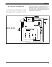
TRANSMITTER ALIGNMENT
The Transmitter consists of synthesizer, exciter,
and power amplifier. These have been calibrated at the
factory so the radio computer automatically adjusts RF
power and modulation deviation, based upon Tracking
Data. The following adjustments can be made by EGE
PC Programming Software:
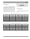
1. Modulation Deviation -- Change Tracking Data using
"MRKMAINT" maintenance software. Follow the
procedure given in "TRACKING DATA" section.
Be sure to record the new Tracking Data and
modulation levels. DO NOT CHANGE TRACKING
DATA UNLESS THE LOGIC OR SYNTHESIZER
HAS BEEN REPLACED. DO NOT CHANGE
TRACKING DATA FOR ANY FREQUENCY
OTHER THAN THAT GIVEN IN TABLES 2 AND
3.
2. RF Power -- Set RF power for system (EDACS) or
channel (CONVENTIONAL) in the radio personality,
using "EDACS3" programming software. DO NOT
CHANGE TRACKING DATA UNLESS THE PA
MODULE OR LOGIC PWB HAS BEEN
REPLACED. DO NOT CHANGE TRACKING
DATA FOR ANY FREQUENCY OTHER THAN
THAT GIVEN IN TABLES 2 AND 3.
There are no other adjustments to be made on the
transmitter. However, there are components located on
the synthesizer and power amplifier, which appear to be
adjustable. These are summarized as follows:
Synthesizer: CV240, CV280, RV201
Power Amp - 25 W: RV1
Power Amp - 50 and 110 W: RV2
These components have been set at the factory, and
are
NOT ADJUSTABLE
. ANY RE-ADJUSTMENT OF
THESE COMPONENTS WILL VOID THE
WARRANTY OF THIS PRODUCT.
NOTICE
The components listed above have been set at the factory
and are NOT adjustable.
ANY RE-ADJUSTMENT OF THESE COMPONENTS WILL
VOID THE WARRANTY OF THIS PRODUCT.
PA TRANSISTOR REPLACEMENT
The RF Power Transistors used in the transmitter
contain Beryllium Oxide, a
TOXIC
substance. If
the ceramic or other encapsulation is opened,
crushed, broken, or abraded, the dust may be
hazardous if inhaled. Use care in replacing
transistors of this type.
WARNING
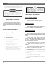
To Replace the PA RF Transistors
1. Unsolder one lead at a time with a 50-watt soldering
iron. Use a scribe or X-acto
knife to hold the lead
away from the printed circuit board until the solder
cools. Remove the mounting screws.
2. Lift out the transistor. Remove any old solder from
the printed circuit board with a vacuum de-soldering
tool. Special care should be taken to prevent damage
to the printed circuit board runs because part of the
matching network is included in the base and
collector runs.
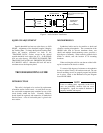
3. Trim the new transistor leads (if required) to the lead
length of the removed transistor.
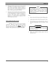
4. Apply a coat of silicone grease to the transistor
mounting surface. Place the transistor in the
mounting hole. Align the leads as shown on the
Outline Diagram. Then replace the transistor
mounting screws using moderate torque (9.4 kg.cm).
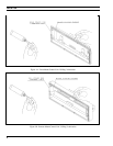
5. Solder the leads to the printed circuit pattern. Start
at the inner edge of the mounting hole and solder the
remaining length of transistor lead to the board. Take
care not to use excessive heat that causes the printed