


LBI-39175
A
17
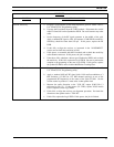
RECEIVER
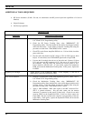
SYMPTOM DIAGNOSTIC PROCEDURE
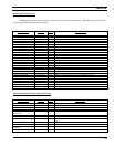
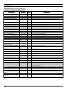
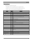
Low RF sensitivity. a. Program a Conventional System with frequencies given in Tables 2 and 3.
Use "EDACS3" PC Programming utility.
b. Unscrew the PA module from the TXRX module. Disconnect the coaxial
cable P2 from J401 on the Synthesizer PWB. Do not disconnect any other
cable.
c. Set the frequency of the RF signal generator to the middle of the split.
Apply a standard RF signal to J401, and measure 12 dB SINAD sensitivity.
Sensitivity should be better than 0.29 µV. If this passes, replace the PA
PWB.
d. If this fails, re-align the receiver, as instructed in the "ALIGNMENT"
section, and re-check the sensitivity at J401
e. If this passes, re-assemble with the PA module and re-check the sensitivity
at the antenna connector. If this passes, the job is complete
f. If the above fails, substitute a known good Synthesizer PWB, and re-check
the sensitivity. If this fails, replace the Logic PWB. Be sure to perform the
complete re-programming on the new Logic PWB. If this passes, replace
the synthesizer PWB, and re-load the Modulation Tracking Data.
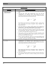
High audio distortion a. Program a Conventional System with frequencies given in Tables 2 and 3.
Use "EDACS3" PC Programming utility.
b. Apply a standard 1000 µV RF signal [with 1 kHz audio modulation at 3
kHz deviation (1.5 kHz for 12.5 kHz channel spacing)] at one of the
programmed RF frequencies in the center of the split to J1001. Set the
volume control to produce 15 watts at the 4-ohm speaker load
c. Measure the audio distortion at the "VOL HI" output (J1003 Pin 13
referenced to Pin 12). If this passes (3% THD), replace IC604 Audio
Power Amplifier on the Logic PWB.
d. If this fails, re-align the receiver per alignment procedure. Re-check the
distortion at the speaker load or "VOL HI."
e. If this fails, replace the Logic PWB. If this passes, the job is finished.