


LBI-39175
A
5
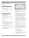
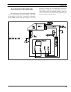
3. Disengage the four captive screws on the rear half
(also known as the Remote Interface Adapter, or
RIA) of the Control Head. Slide the two halves
apart, using care to avoid damaging the black "O-
Ring" moisture gasket attached to the RIA.
4. Disconnect Flex Circuit PC2 from Connector J2, by
carefully disengaging the locking tab from each side
of the connector with a jeweler's screwdriver or
tweezers. Use extreme care to avoid damaging
plating runs or surface-mounted components in the
PWB during this procedure.
To Re-Assemble Unit after Servicing
Essentially follow the reverse of the preceding
instructions. However, in order to preserve moisture
seals, be sure to follow the EXACT torque and
sequencing specifications for screw engagement during re-
assembly. These specifications are given in LBI-38909.
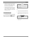
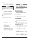
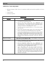
For re-assembly of the Control Units (Front and
Remote Mounting) Revision "A" or later, be sure
the black "O-Ring" is lubricated properly with
"HIVAC-G" silicone grease. (See Figures 1A and
1B for intructions.)
NOTE
Steps:
1. Remove dust and dirt from the black O-Ring gasket.
2 Apply proper amount of the silicone grease to cloth.
3. Put the silicone grease on throughout the surface of
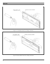
the black O-Ring gasket evenly. (see Figures 1A and
1B)
No fibers of the cloth must remain on the gasket
after silicone is applied.
CAUTION
4. Wipe out protruded silicone grease from the
Rear/RIA Cover.