


©2007 ELAN Home Systems • All Rights Reserved 13
¸
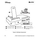
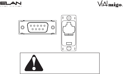
12345
6789
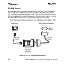
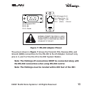
RS-232 Adapter DB-9
Pin 2 = TX
Pin 3 = RX
Pin 5 = Ground
RS-232 Adapter RJ-45
Pin 2 (Blue White) = TX
Pin 3 (Orange) = RX
Pin 5 (Green) = Ground
12345678
WARNING: CONNECT ONLY PINS 2, 3, AND 5.
DO NOT CONNECT OTHER PINS TO THE SS1.
CONNECTING TO OTHER PINS WILL RESULT
IN DAMAGE TO THE UNIT!
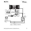
Figure 7: RS-232 Adapter Pinout
The pinout shown in Figure 7 shows the Transmit (TX), Receive (RX), and
Ground (GND) connections for the RS-232 to RJ-45 Adapter. Connect only
pins 2, 3, and 5 of the RJ-45 to the SS1 System Station.
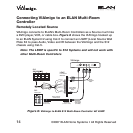
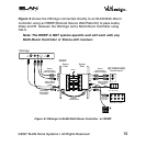
Note: The VIA!migo IR connections MUST be connected along with
the RS-232 connections when using RS-232 control.
Note: The VIA!migo must be located within 300 feet of the SS1.