12
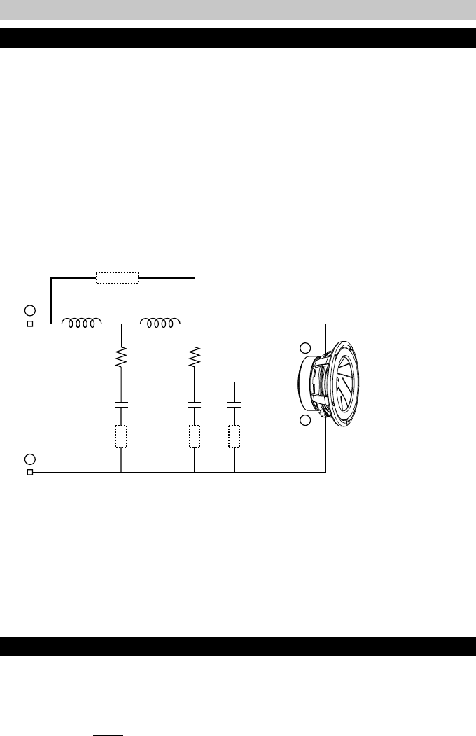
WF-LP:
While functioning as a low-pass filter for the woofer, this section also provides a wide
degree of adjustments for optimizing performance and system integration. Since it is
often difficult to position the woofer and midrange close together or at equal distances,
it is critical to achieve phase linkage between them to avoid localization, image smear,
poor staging, etc. Additionally, vehicle interior dimensions are typically close to the wave-
length of the woofer/midrange crossover region, so it may be necessary to minimize
overlap to reduce the chance of generating a complex canceling sound field or re-
sponse aberrations. Therefore, a variety of higher order filter types and characteristics
are provided in this section, making it possible to link the two drivers in relative phase
for a smooth transition in many applications. Again, it is important to note that the selec-
tions made in both the WF-LP and MID-HP sections produce a net effect, and must be
set in such a way so as to work together. As a general reference, the available woofer
low-pass filter configurations are listed below.
R9 = 2.2Ω
R10 = 1.5Ω
C6 = 100µF
C7 = 47µF
C8 = 220µF
L6 = 0.65mH
L7 = 0.65mH
BYPASS
L6 L7
R10R9
C7C6 C8
LP-1
LP-2
LP-3
+
–
+
–
SIGNAL LINK:
The signal link jumpers provide a parallel connection between the input sides of the
terminal blocks, eliminating the need for extra terminals or wiring when using a single or
dual input.
Caution:
These jumpers
must be removed accordingly when used in a bi-amp or tri-amp
configuration to prevent possible damage to amplifiers.
1
st
Order:
• No HP jumpers
2
nd
Order:
• LP2
• LP3
• LP2 + LP3
3
rd
Order:
• LP1
4
th
Order:
• LP1 + LP2
• LP1 + LP3
• LP1 + LP2 + LP3
Jumper Group Function


