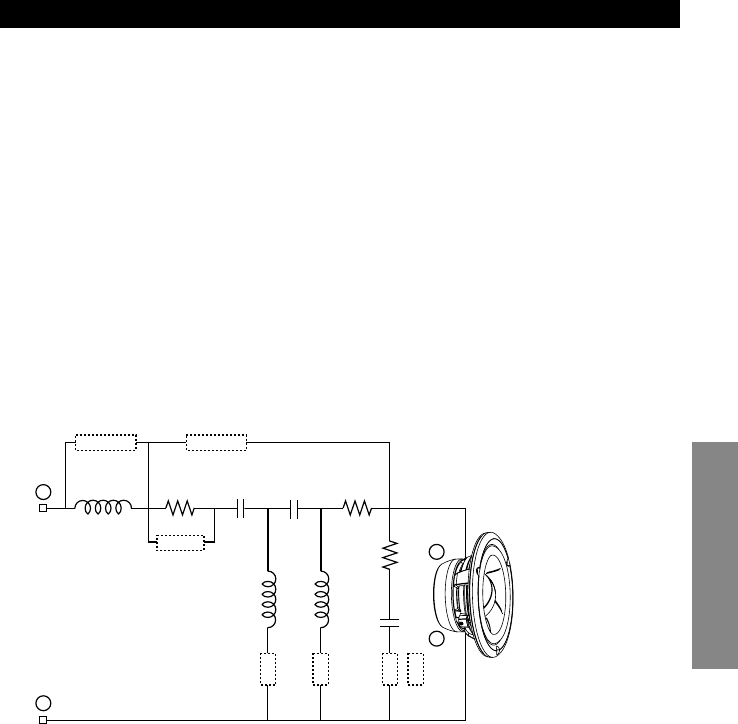
11
English
R6 = 1.0Ω
R7 = 1.0Ω
R8 = 22Ω
C3 = 18µF
C4 = 33µF
C5 = 10µF
L3 = 0.32mH
L4 = 2.0mH
L5 = 2.9mH
MID HP/LP:
As a selectable bandpass filter for the midrange, the net effect of this section is naturally
linked to the selections made in the tweeter high-pass and woofer low-pass sections.
Achieving the most phase coherent and flat summation possible requires controlling
the amount of inherent phase shift of each filter, and is directly related to the selection of
filter order, Q and cut-off frequency. Again, this relationship is also affected by the dis-
tance and angle of each driver relative to the listener and their proximity to each other.
Since the acoustic center of the midrange will be farther back than the tweeter in nearly
all applications, minimal delay is desirable in the midrange low-pass. Subsequently, this
filter is of low order, and leaves much of the adjustment capability for the mid/tweeter
transition to the tweeter high-pass section. For the midrange high-pass, higher order
configurations are used in most applications to achieve phase linkage with the woofer
(see WF-LP section). For general reference, the available midrange network configura-
tions are listed below. In certain installations where positioning or placement necessi-
tates level adjustment, a jumper is provided that boosts midrange output by approxi-
mately +2dB. As an additional note, either filter (high-pass or low-pass) may be by-
passed independently for semi-active applications.
HP-2
HP BYPASS
LP BYPASS
+2dB
L4 L5
C3R6
L3
C4 R7
R8
C5
HP-1
LP-2
LP-1
+
–
+
–
1
st
Order HP:
• No HP jumpers
• HP2 (semi-2
nd
Order)
1
st
Order LP:
• LP1
• LP2
3
rd
Order HP:
• HP1
4
th
Order HP:
• HP1 + HP2


