6-6 Chapter 6
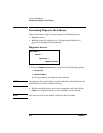
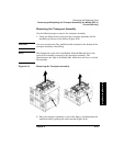
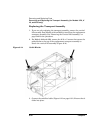
Removing and Replacing Parts
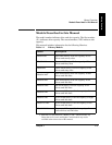
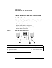
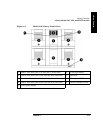
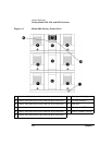
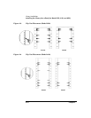
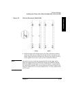
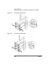
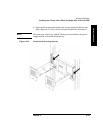
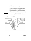
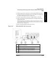
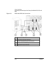
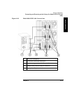
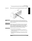
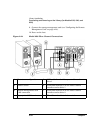
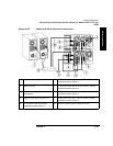
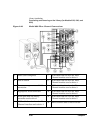
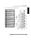
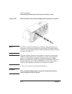
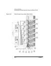
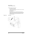
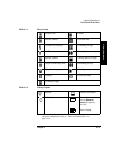
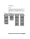
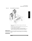
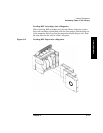
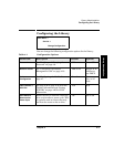
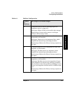
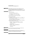
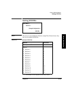
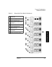
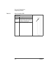
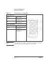
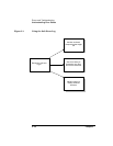
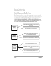
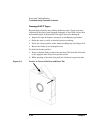
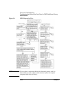
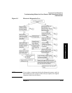
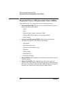
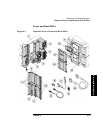
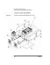
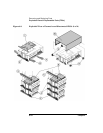
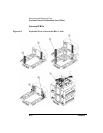
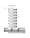
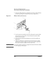
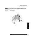
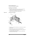
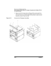
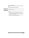
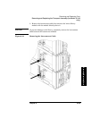
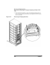
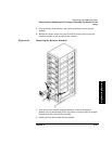
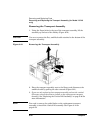
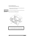
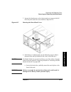
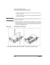
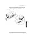
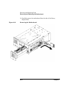
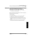
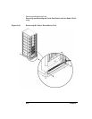
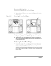
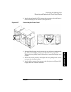
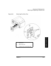
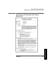
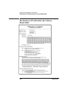
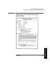
Exploded Views of Replaceable Parts (FRUs)
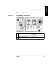
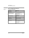
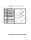
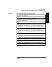
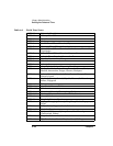
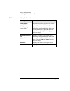
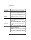
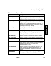
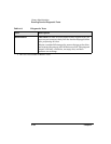
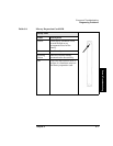
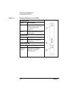
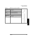
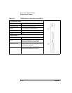
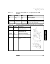
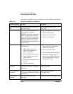
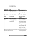
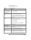
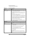
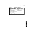
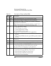
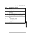
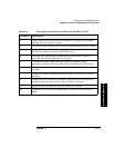
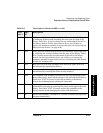
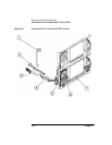
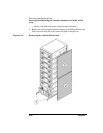
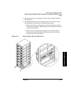
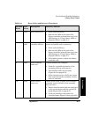
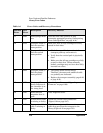
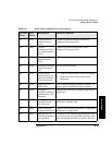
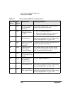
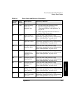
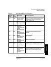
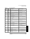
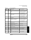
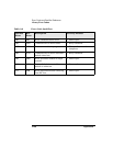
Table 6-2 Description of Front and Back FRUs
Call-
out #
FRU
ID
Description
1 N/A Vacant drive module cover: Uses two 6-32 screws to attach.
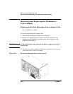
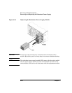
2 32 Standard power supply (see page 6-56 for more information).
3 32 Redundant power supply: Uses 6-32 x .25 T15 screws to attach (see
page 6-58 for more information).
Note: Libraries should only contain all redundant or standard power
supplies. The illustration is for identification purposes only.
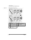
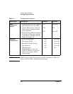
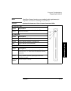
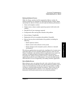
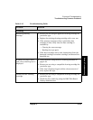
42 • DLT LVDS tape drive module.
• DLT HVDS tape drive module.
• Ultrium LVDS tape drive module.
• Ultrium HVDS tape drive module.
(See page 6-21 for more information on drive replacement.)
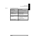
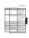
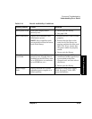
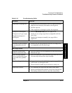
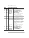
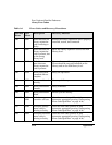
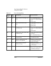
562 • DLT or Ultrium LVDS online drive repair SCSI loop cable (included in
cable kit).
• DLT or Ultrium HVDS online drive repair SCSI loop cable (included in
cable kit).
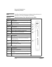
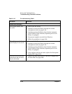
6 6 Slave controller for all models, except Model 2/20 (see page 6-18 for more
information).
7 N/A Vacant card slot cover.
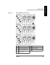
8 7 Remote management card assembly (see page 6-18 for more information).
91 • Low Voltage Differential SCSI (LVDS) library controller.
• High Voltage Differential SCSI (HVDS) library controller.
(See page 6-18 for more information on card replacement.)
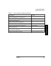
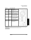
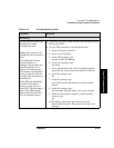
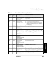
10 9 • Standard performance HVDS Fibre Channel board.
• Standard performance LVDS Fibre Channel board.
• High performance HVDS Fibre Channel board.
• High performance LVDS Fibre Channel board.
(See page 6-18 for more information.)